Current sensor

a current sensor and sensor technology, applied in the field of current sensors, can solve the problems of unstable detection of current sensors and lowered current detection accuracy, and achieve the effect of lowering current detection accuracy

Inactive Publication Date: 2011-03-24
KK TOKAI RIKA DENKI SEISAKUSHO
View PDF11 Cites 42 Cited by
  • Summary
  • Abstract
  • Description
  • Claims
  • Application Information

AI Technical Summary

Benefits of technology

[0007]The bus bar 40 of the prior art sensor is just inserted into the sleeve 34a. Thus, the bus bar 40 may slightly move inside the sleeve 34a. Such displacement of the bus bar 40 changes the positional relationship between the magnetic core 31 and the bus bar 40. This changes the electric field that is concentrated and amplified by the magnetic core 31. As a result, the current sensor detection may become unstable, and the current detection accuracy may be lowered.

Problems solved by technology

As a result, the current sensor detection may become unstable, and the current detection accuracy may be lowered.

Method used


Image

  • Current sensor
  • Current sensor
  • Current sensor

Examples


Embodiment Construction

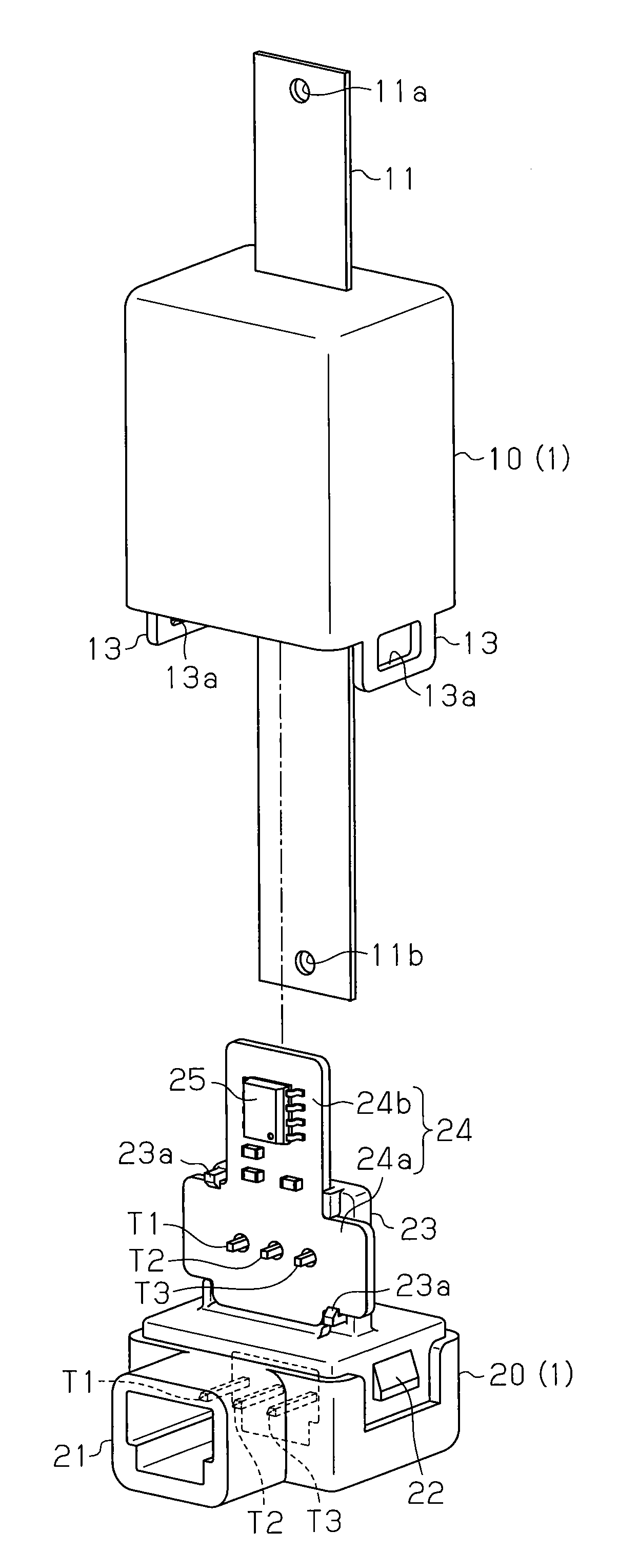
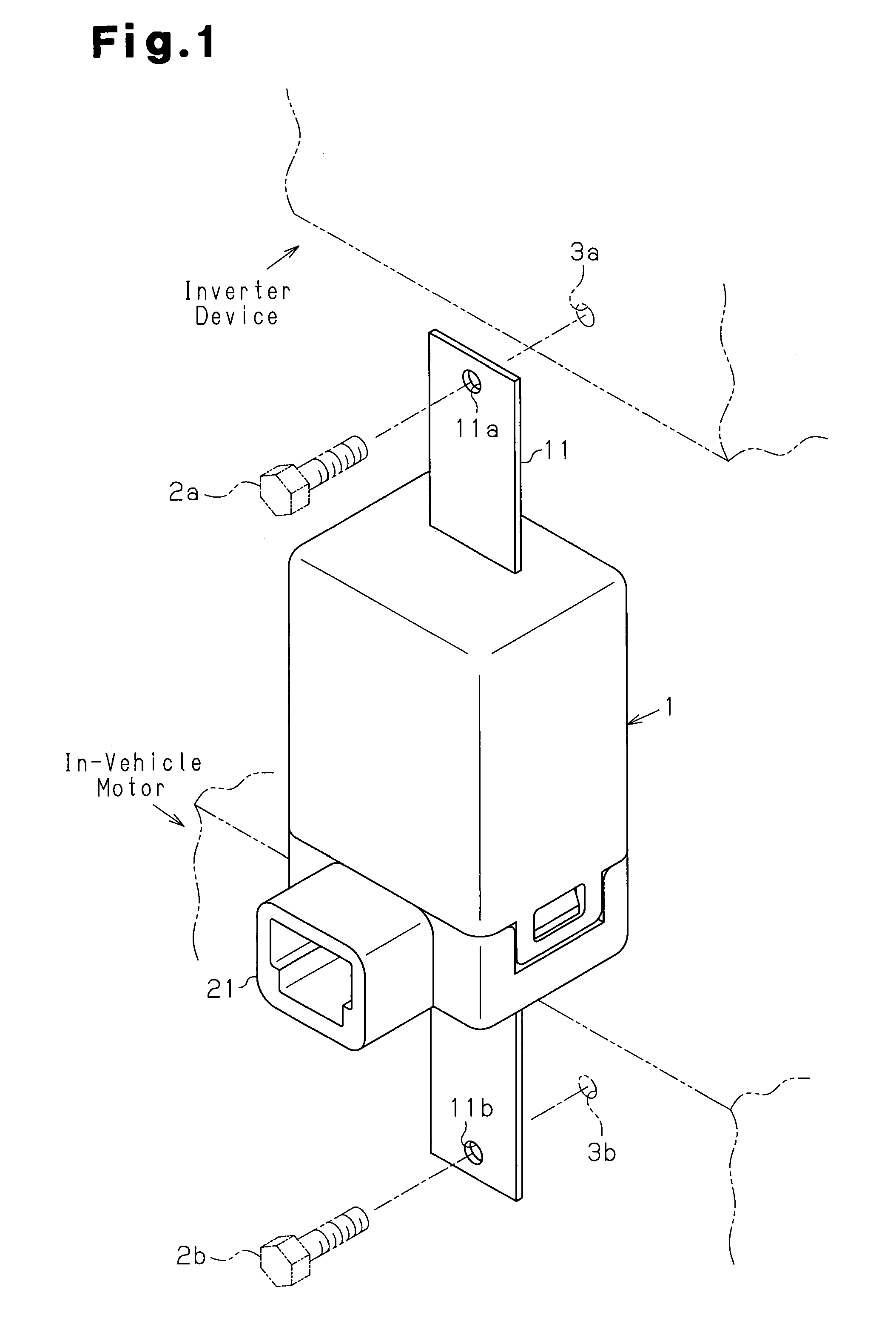
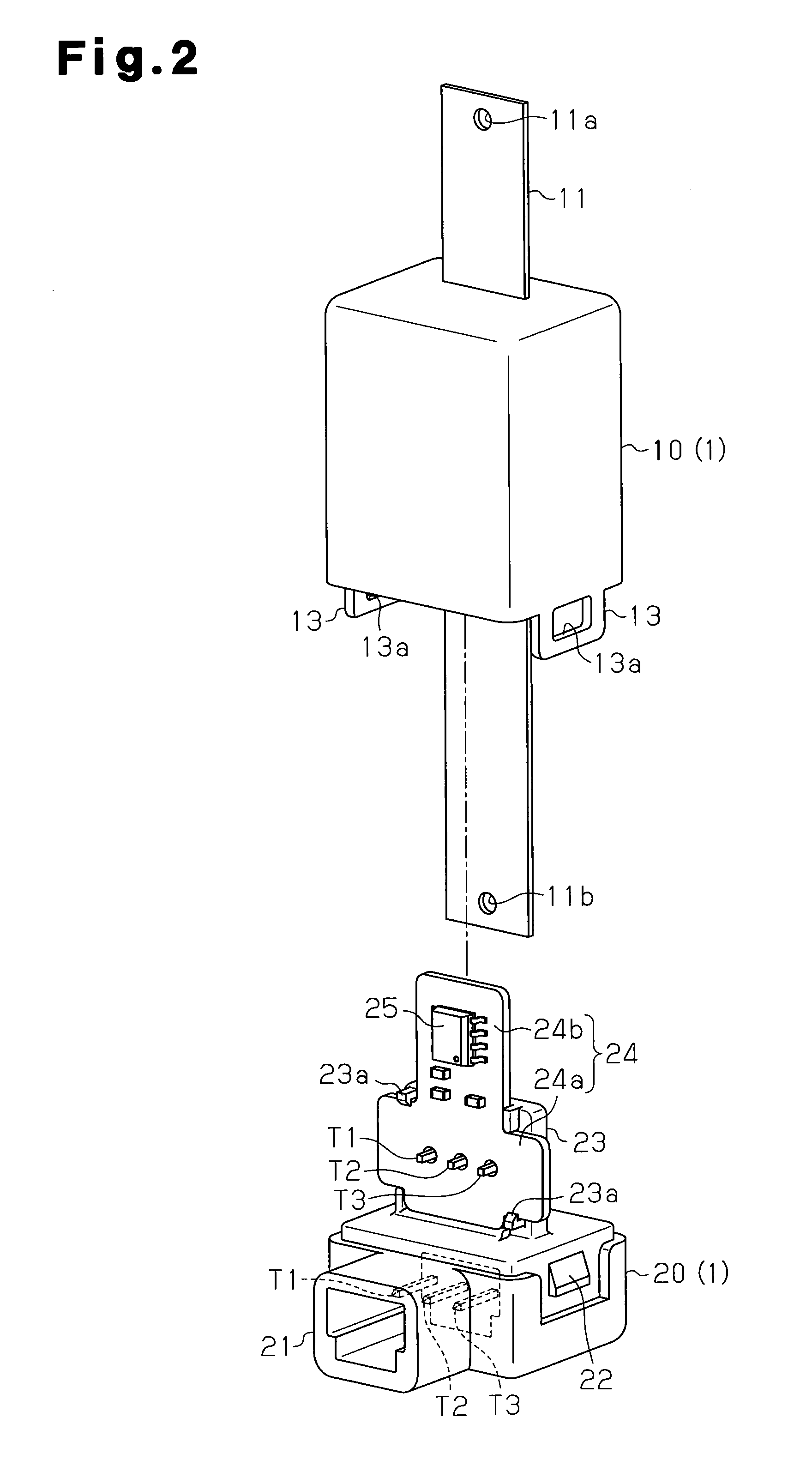
[0021]A current sensor according to one embodiment of the present invention will now be discussed with reference to FIGS. 1 to 4. First, the structure of the current sensor will be described with reference to FIG. 1.

[0022]As shown in FIG. 1, a case 1 covers electronic components of the current sensor. The case 1 protects the electronic components from the ambient environment. A connector 21 is arranged on the front of the case 1. The connector 21 is connected to a harness or the like (not shown) and may be used to supply the current sensor with power and to output a detection signal of the current sensor to an external device. A bus bar 11 having an elongated planar shape is attached to the case 1 in a state extending vertically through the case 1 as viewed in the drawing. The bus bar 11 is a power supply conductor and connects, for example, an in-vehicle inverter device and an in-vehicle motor. The bus bar 11 includes end portions that define coupling portions for coupling the curr...


PUM


Abstract

A current sensor for outputting a detection signal corresponding to a current flowing through a bus bar. The current sensor includes a magnetic core that concentrates and amplifies a magnetic field generated by the current near a detection portion of the bus bar. A magnetic detection element detects the magnetic field concentrated by the magnetic core and outputs an electrical signal corresponding to the detected magnetic field. The detection portion of the bus bar and the magnetic core are molded integrally with each other.

Description

CROSS-REFERENCE TO RELATED APPLICATIONS[0001]This application is based upon and claims the benefit of priority from prior Japanese Patent Application No. 2009-217745, filed on Sep. 18, 2009, the entire contents of which are incorporated herein by reference.BACKGROUND OF THE INVENTION[0002]The present invention relates to a current sensor for detecting the magnitude of electric current flowing through a conductor.[0003]A known current sensor uses a magnetic detection element such as a Hall element or a magnetoresistance effect element. The current detection performed by a current sensor that uses a Hall element will now be described.[0004]When current flows through a current path such as a wire, the current forms a magnetic field near the current path. The strength of the magnetic field is proportional to the magnitude of the current. When a Hall element is arranged in the magnetic field formed near the current path, the Hall element generates a Hall voltage that is proportional to t...

Claims


Application Information

Patent Timeline
Patent Type & Authority Applications(United States)
IPC IPC(8): G01R15/18
CPCG01R15/202G01R15/207G01R15/205
Inventor UENO, HIROSHIINAGAKI, YUJI
Owner KK TOKAI RIKA DENKI SEISAKUSHO
Why Eureka
Try Eureka