
Estimating porosity and fluid volume

a fluid volume and porosity technology, applied in wave based measurement systems, instruments, reradiation, etc., can solve the problems of unfavorable continuous nuclear magnetic resonance logging, unfavorable continuous shale gas logging, and unfavorable logging techniques, so as to increase the signal-to-noise ratio and the signal-to-noise ratio. , the effect of increasing the signal-to-noise ratio

Active Publication Date: 2011-03-24
SCHLUMBERGER TECH CORP
View PDF10 Cites 49 Cited by
  • Summary
  • Abstract
  • Description
  • Claims
  • Application Information

AI Technical Summary

Benefits of technology

[0009]The present disclosure relates to a method to estimate a subsurface formation property. A downhole logging tool is provided and disposed in a wellbore. Multiple measurements of various measurement types are obtained at various depths of investigation using the downhole logging tool. The multiple measurements may include natural gamma ray measurements, density measurements, resistivity measurements, nuclear measurements, and nuclear magnetic resonance measurements. The signal-to-noise ratio of the measured signals is increased using, for example, lateral stacking and multi-shell inversion. The subsurface formation property is estimated using the increased signal-to-noise ratio signals. The subsurface formation property may include porosity, adsorbed gas volume, free gas volume,...

Problems solved by technology

However, this technique has not possible to be applied to tight shale gas formations because of the low signal-to-noise ratio associated with such formations.
Those factors contribute to a weak measured signal while the noise level is generally high because of high formation temperatures, thereby making the signal-to-noise ratio unfavorable to continuous nuclear magnetic resonance logging.

Method used


Image

  • Estimating porosity and fluid volume
  • Estimating porosity and fluid volume
  • Estimating porosity and fluid volume

Examples


Embodiment Construction

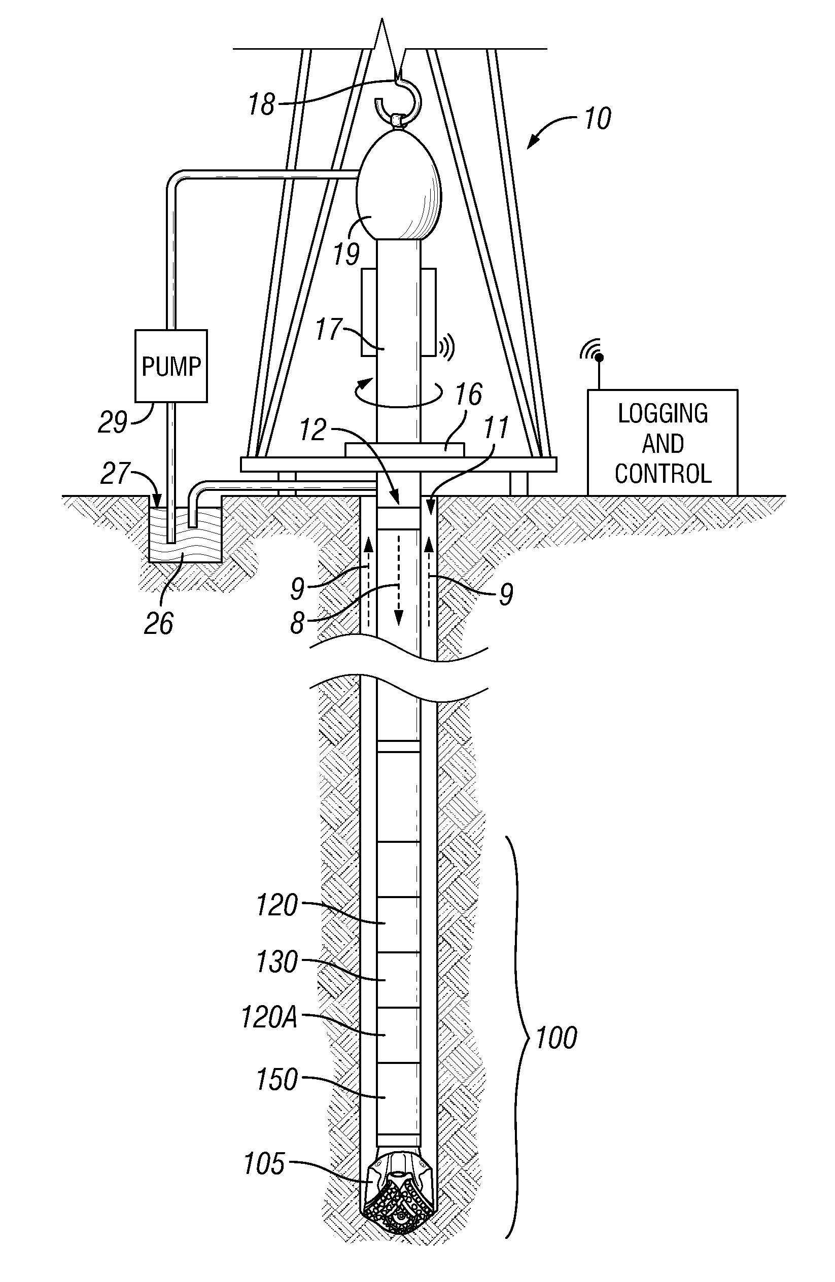
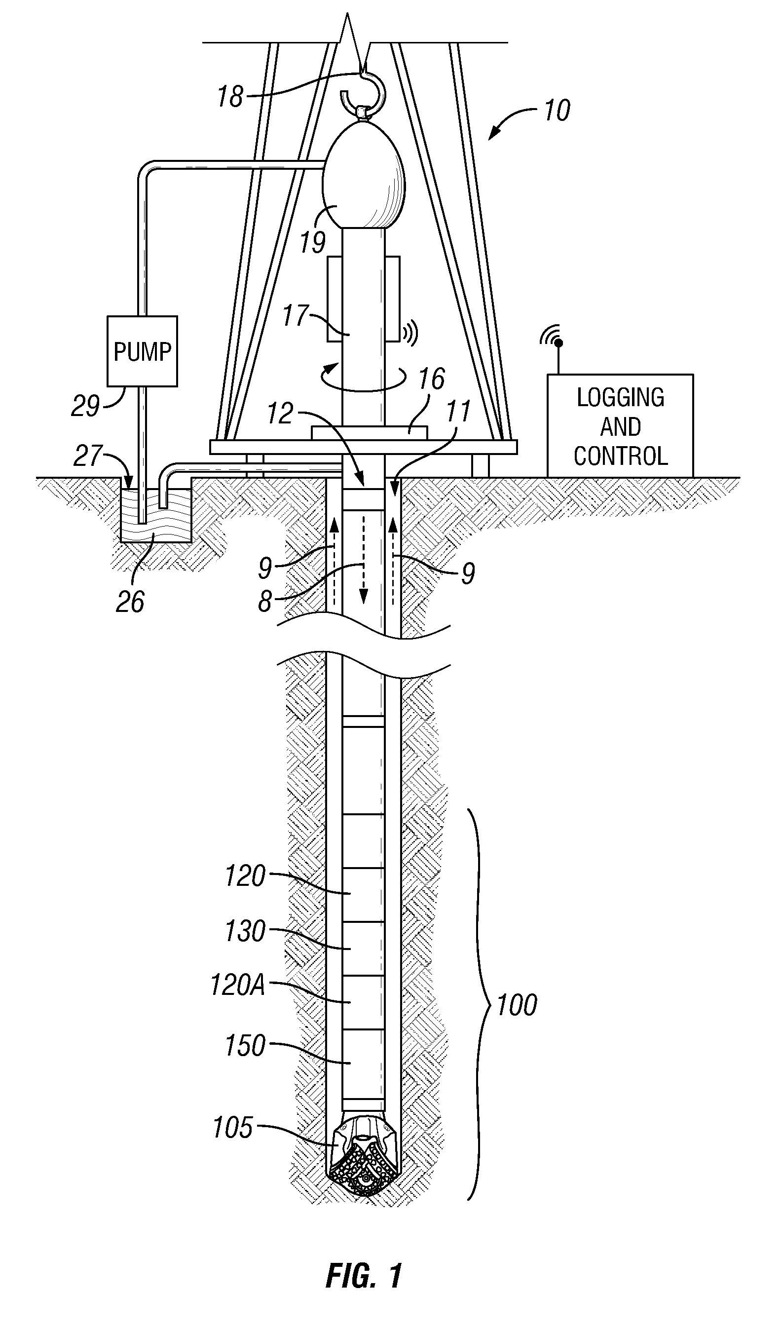
[0016]Some embodiments will now be described with reference to the figures Like elements in the various figures will be referenced with like numbers for consistency. In the following description, numerous details are set forth to provide an understanding of various embodiments and / or features. However, it will be understood by those skilled in the art that some embodiments may be practiced without many of these details and that numerous variations or modifications from the described embodiments are possible. As used here, the terms “above” and “below”, “up” and “down”, “upper” and “lower”, “upwardly” and “downwardly”, and other like terms indicating relative positions above or below a given point or element are used in this description to more clearly describe certain embodiments. However, when applied to equipment and methods for use in wells that are deviated or horizontal, such terms may refer to a left to right, right to left, or diagonal relationship as appropriate.

[0017]FIG. 1...


PUM


Abstract

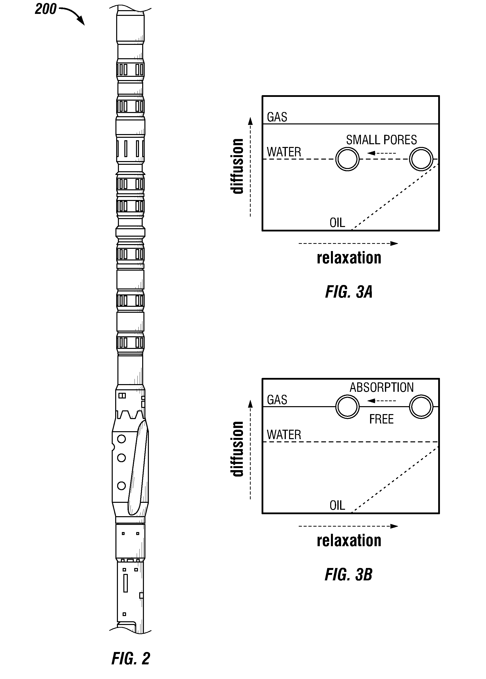
The present disclosure relates to a method to estimate a subsurface formation property. A downhole logging tool is provided and disposed in a wellbore. Multiple measurements of various measurement types are obtained at various depths of investigation using the downhole logging tool. The multiple measurements may include natural gamma ray measurements, density measurements, resistivity measurements, nuclear measurements, and nuclear magnetic resonance measurements. The signal-to-noise ratio of the measured signals is increased using, for example, lateral stacking and multi-shell inversion. The subsurface formation property is estimated using the increased signal-to-noise ratio signals. The subsurface formation property may include porosity, adsorbed gas volume, free gas volume, bound water volume, free water volume, oil volume, and kerogen volume. A fluid analysis may be performed using a multi-dimensional nuclear magnetic resonance technique. Fluids such as water, oil, gas, and oil-based mud in the wellbore may be identified and / or evaluated.

Description

CROSS-REFERENCE TO OTHER APPLICATIONS[0001]This application claims, under 35 U.S.C. 119(e), priority to and the benefit of U.S. Provisional Application No. 61 / 245,103, filed Sept. 23, 2009.BACKGROUND[0002]1. Technical Field[0003]The present disclosure relates generally to the logging of subsurface formations surrounding a wellbore using a downhole logging tool, and particularly to using the logs to estimate one or more formation properties.[0004]2. Background Art[0005]Logging tools have long been used in wellbores to make, for example, formation evaluation measurements to infer properties of the formations surrounding the borehole and the fluids in the formations. Common logging tools include electromagnetic tools, nuclear tools, and nuclear magnetic resonance (NMR) tools, though various other tool types are also used.[0006]Early logging tools were run into a wellbore on a wireline cable, after the wellbore had been drilled. Modern versions of such wireline tools are still used exte...

Claims


Application Information

Patent Timeline
IPC IPC(8): G01V3/175
CPCG01V3/18Y02A90/30
Inventor MINH, CHANH CAO
Owner SCHLUMBERGER TECH CORP
Learn More