Imaging system and device

a technology of imaging system and lens, applied in the field of imaging system and device, can solve the problems of difficult distortion of a tailored distortion lens through the design of the optics, unavoidable geometric lens distortion, and difficult to see significant amount of distortion, so as to preserve the overall field of view and expand or shrink the central section of the imag

Active Publication Date: 2011-03-24
NING ALEX
View PDF4 Cites 39 Cited by
  • Summary
  • Abstract
  • Description
  • Claims
  • Application Information

AI Technical Summary

Benefits of technology

[0012]In one embodiment a new “zooming” method is disclosed. This new zooming method allows one to enlarge or shrink the central section of the image while still preserving the overall field of view. Applications of this invention are in imaging systems such as endoscopes, automotive applications and security cameras. Zooming while maintaining the field of view is accomplished with digital processing hardware and software. An image (video frame) is captured by a lens having known optical properties. This image is processed digitally to enlarge or shrink the central portion of the image producing a transformed image. In one embodiment the calculation is constrained such that the transformed image will have the same overall field of view as the originally acquired image. This means that the off-axis image is squeezed or stretched to accommodate the zooming of the central portion of the image. The transition between center and periphery is smooth and continuous. While the central portion is “zoomed in”, the periphery is “zoomed out” and vice versa. The image is captured by an electronic imager (for example, a CCD or CMOS imager) located at the focal plane of the lens. The electronic image is then manipulated using processing algorithms programmed into the same processor that acquires the images or optionally a second processor. The second processor may be remotely located from the processor that acquires the images initially.

Problems solved by technology

As the field of view increases, geometric lens distortion becomes un-avoidable.
However, sometimes significant amount of distortion can still be easily seen even in a tailored distortion lens.
To further reduce the distortion of a tailored distortion lens through the design of the optics is very difficult and may require undesirable compromises of other lens parameters.
When a smaller section is enlarged, one loses field of view because image areas outside the zoomed area can no longer be displayed.
This adds to the complexity of procedures and increases the chance for contamination and infection.
These more complex probes can often lead to a surgeon missing particular features as the field of view is narrowed or the field of view is limited to a particular direction.
Geometric distortions in such images may result in effectively blind spots similar to those that the systems are intended to eliminate.
None of these attempts address the needs discussed above.

Method used


Image

  • Imaging system and device
  • Imaging system and device
  • Imaging system and device

Examples


Embodiment Construction

[0033]The term “lens element” means a single transparent mass of refractive material having two opposing refracting surfaces. An aspheric element is a lens element having at least one refracting surface that is neither spherical nor flat. The term “lens component” is defined as (a) a single lens element spaced so far from any adjacent lens element that the spacing cannot be ignored in computing the optical properties of the lens assembly, or (b) two or more lens elements that have their adjacent lens surfaces either in full overall contact or overall so close together that the spacing between adjacent lens surfaces can be ignored in computing the overall lens assembly performance. Lens elements and lens components are identified numerically increasing from object to image.

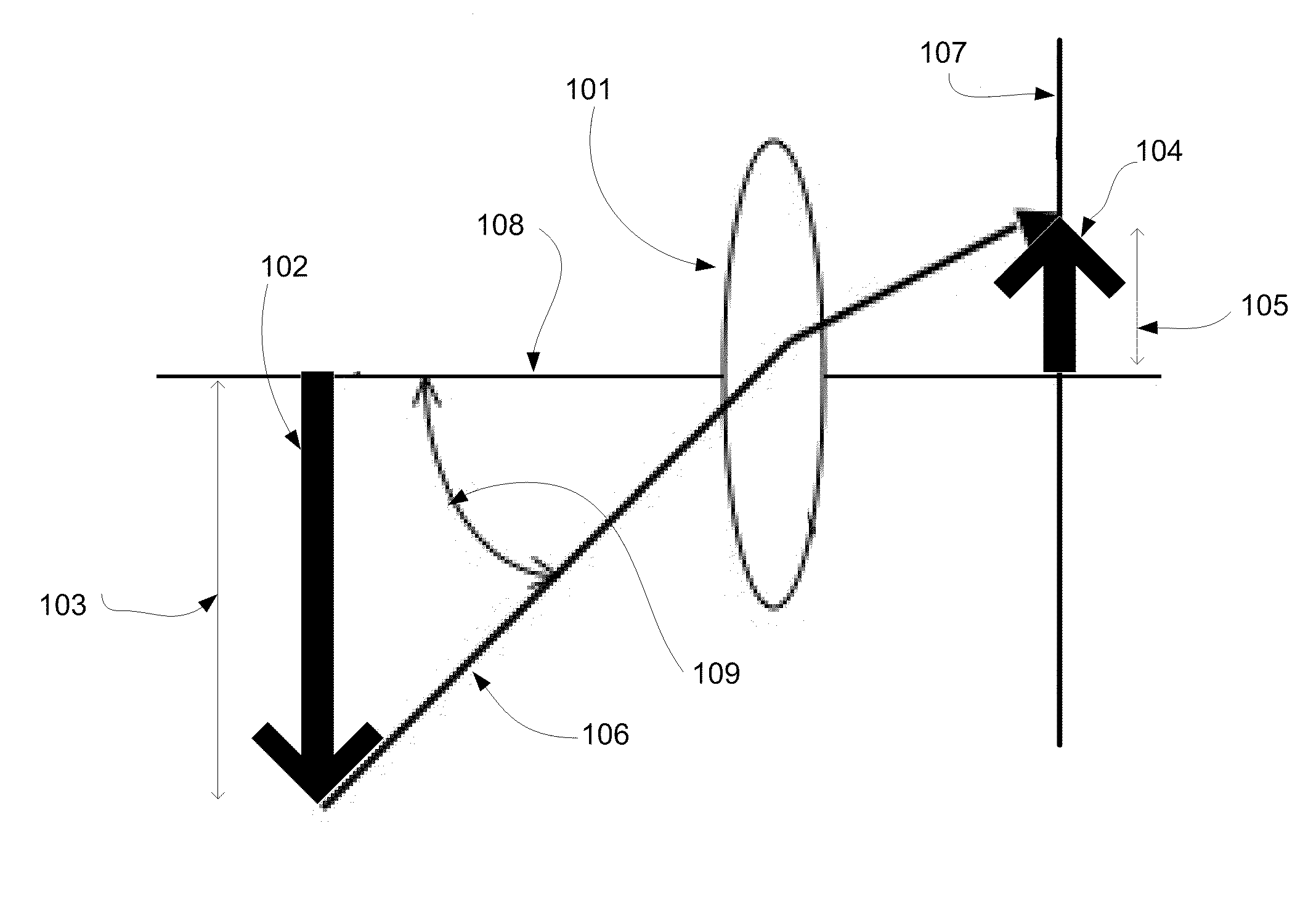
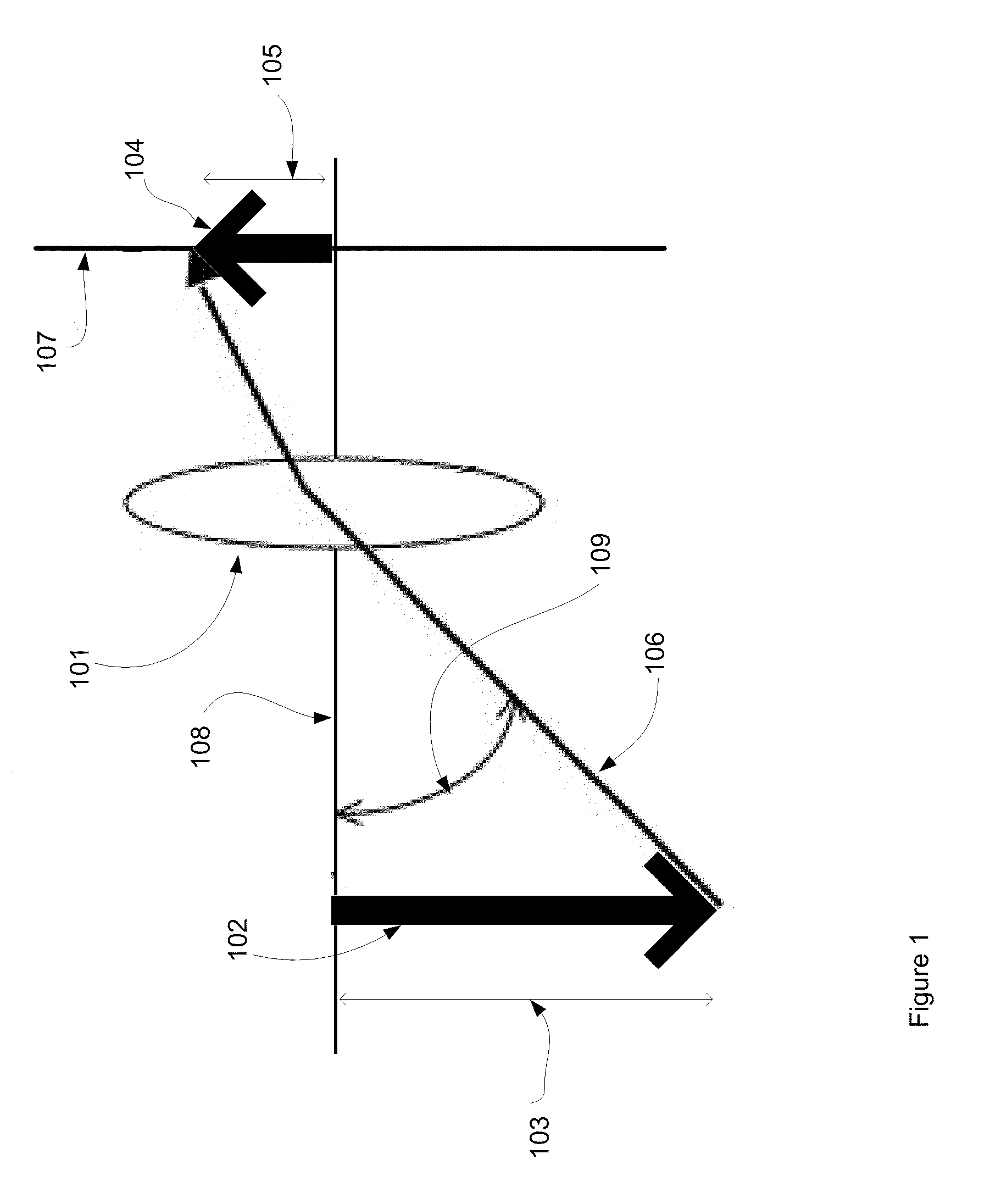
[0034]FIG. 1 shows the functionality of a lens. An object 102 is imaged by a lens system 101 having an optical axis 108. The lens system 101 may consist of a single lens element or multiple lens elements. A single ...


PUM


Abstract

An imaging system and method of application, including lens designs tailored to be used with particular transformation algorithms, electronic hardware and algorithms for image transformations is described. Exemplary application of the system including automotive, photographic and medical endoscopic are also described. The system enables improved image view and allows customization of views by the end user even after installation of the image system hardware.

Description

CROSS-REFERENCE TO RELATED APPLICATIONS[0001]This application claims the benefit of U.S. Provisional Patent Application 61 / 245,565, filed Sep. 21, 2009, entitled “Wide-Angle Imaging System and Device”, currently pending, by the same inventor, and incorporated by reference.BACKGROUND OF THE INVENTION[0002]1. Technical Field[0003]The present invention relates to an imaging system and devices for medical, automotive, photographic and other applications.[0004]2. Related Background Art[0005]Wide-angle lenses are useful for a variety of applications including medical application such as endoscopes, security cameras, automotive cameras and imaging systems for photography. As the field of view increases, geometric lens distortion becomes un-avoidable. The straight lines at the off-axis field points become curved. Distortion can be minimized with appropriate lens design. Lenses are also designed with particular geometric distortion properties to match the application. Lenses may be designed ...

Claims


Application Information

Patent Timeline
Patent Type & Authority Applications(United States)
IPC IPC(8): H04N7/18G02B13/18H04N5/225G06K9/36
CPCA61B1/00188G02B13/04G06T3/0031G02B27/0012G06T5/006G02B23/243
Inventor NING, ALEX
Owner NING ALEX
Why Eureka
Try Eureka