
Optical designs for zero order reduction

a technology of optical designs and zero order reduction, applied in the field of optical pattern generation, can solve the problems of poor uniformity of a projection method, unusable for certain applications, and may suffer from the so-called zero order problem

Inactive Publication Date: 2011-03-24
APPLE INC
View PDF32 Cites 42 Cited by
  • Summary
  • Abstract
  • Description
  • Claims
  • Application Information

AI Technical Summary

Benefits of technology

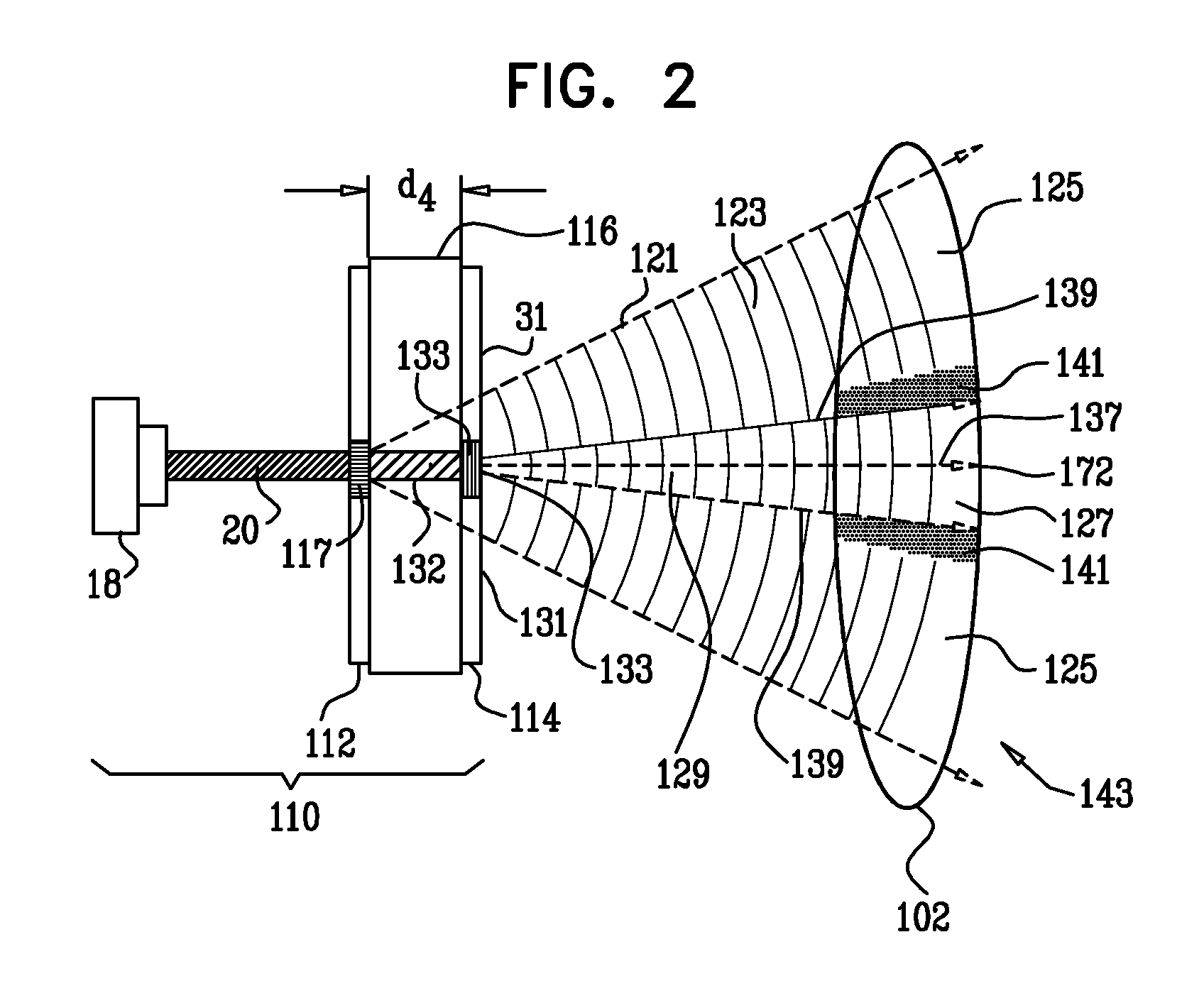
The present invention relates to an apparatus for projecting a pattern using two diffractive optical elements (DOE) that work together to generate diffraction patterns. By using two DOE's, the system can generate a more efficient and efficient pattern compared to using a single DOE. The two DOE's can be positioned in a way that their diffraction patterns overlap, resulting in a reduced peak-to-average power ratio and improved efficiency. The diffraction patterns generated by the two DOE's can also have enhanced overall efficiency compared to a single DOE. The first and second regions can be different, and the first and second diffraction patterns can be directed to different regions on the surface. The invention can be applied in optical systems that contain both refractive and diffractive elements.

Problems solved by technology

Poor uniformity of a projection method may render it unusable for certain applications, such as those applications in which the projected pattern can be seen by the user.
However, the DOEs may suffer from the so-called zero order problem.

Method used


Image

  • Optical designs for zero order reduction
  • Optical designs for zero order reduction
  • Optical designs for zero order reduction

Examples


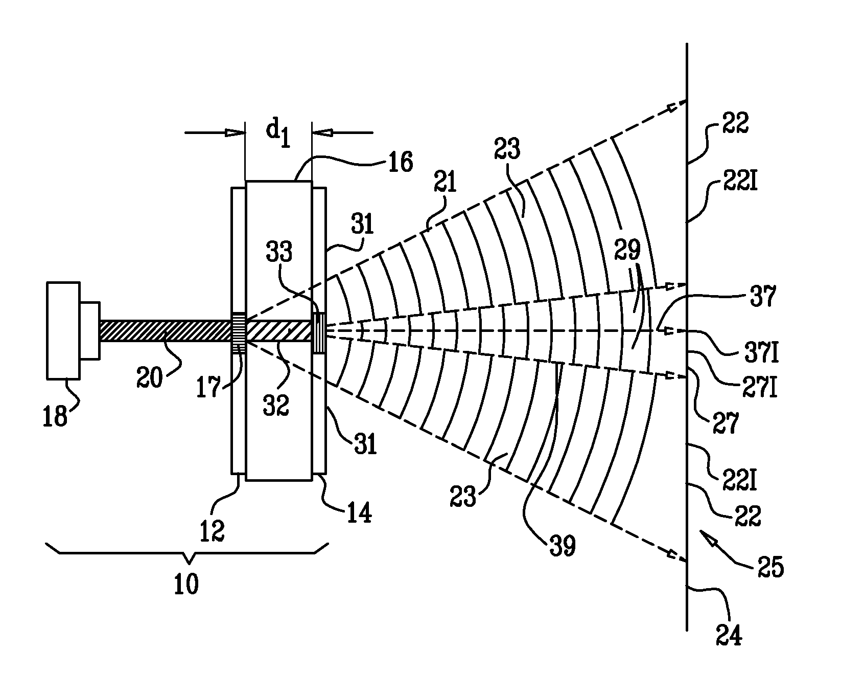
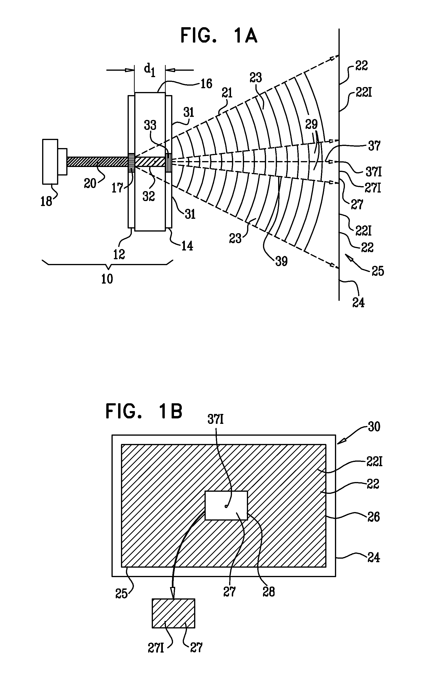
Embodiment Construction

[0030]In the specification and in the claims, a tiling of a region of a plane is assumed to comprise a collection of plane figures, or tiles, that fill the region with no significant overlaps and with no significant gaps.

[0031]Reference is now made to FIG. 1A, which is a schematic side view of an optical apparatus 10, and to FIG. 1B, which is a schematic diagram illustrating regions upon which apparatus 10 projects, according to an embodiment of the present invention. Apparatus 10 comprises a first diffractive optical element (DOE) 12, and a second DOE 14. By way of example, in the following description DOE 12 and DOE 14 are assumed to be substantially parallel to each other, being separated by a distance “d1.” However, the two DOEs do not need to be parallel to each other, and may be aligned with respect to each other at any convenient angle. In apparatus 10 DOE 12 and DOE 14 are assumed, by way of example, to be formed on first and second surfaces of a single transparent optical e...


PUM


Abstract

Apparatus for projecting a pattern includes a first diffractive optical element (DOE) configured to diffract an input beam so as to generate a first diffraction pattern on a first region of a surface, the first diffraction pattern including a zero order beam. A second DOE is configured to diffract the zero order beam so as to generate a second diffraction pattern on a second region of the surface such that the first and the second regions together at least partially cover the surface.

Description

RELATED APPLICATION[0001]This application claims the benefit of U.S. Provisional Patent Application No. 61 / 022,482, titled “Optical Designs for Zero-Order Reduction,” filed Jan. 21, 2008, which is incorporated herein by reference.FIELD OF THE INVENTION[0002]The present invention relates generally to optical pattern generation, and specifically to optical pattern generation with reduced uncontrolled zero order energy, particularly (but not exclusively) in configurations using diffractive optical elements.BACKGROUND OF THE INVENTION[0003]Efficient optical projection of patterns is used in diverse applications such as optical three dimensional (3D) mapping. Such a mapping generates a 3D profile of the surface of an object by processing its optical image. The desired properties of the projected patterns generally depend on the application, but typically include high contrast, high projection efficiency and high uniformity of intensity distribution between the projected beamlets that mak...

Claims


Application Information

Patent Timeline
Patent Type & Authority Applications(United States)
IPC IPC(8): G02B5/18
CPCG02B27/0944G03B35/00G02B27/4266G02B27/4233G02B27/425G02B27/4272G02B27/4277
Inventor SHPUNT, ALEXANDER
Owner APPLE INC
Learn More