Active boost power converter for single-phase srm

Inactive Publication Date: 2011-03-24
KYUNGPOOK NAT UNIV IND ACADEMIC COOP FOUND
View PDF5 Cites 11 Cited by
  • Summary
  • Abstract
  • Description
  • Claims
  • Application Information

AI Technical Summary

Benefits of technology

[0019]As described above, according to the present invention, the boost module is provided to make voltage of the first capacitor equal to dc-link voltage and first and second capacitors are controlled to be operated in series or parallel by simply controlling the IGBT, so that high excitation voltage is applied to rapidly establish excitation current in the excitation mode and high demagnetization voltage is applied to reduce tail current and negative to

Problems solved by technology

In addition, the four-level converter requires a voltage detection circuit for controlling the boost vol

Method used


Image

  • Active boost power converter for single-phase srm
  • Active boost power converter for single-phase srm
  • Active boost power converter for single-phase srm

Examples


Example

[0030]Hereinafter, a single-phase SRM driving apparatus according to the exemplary embodiments of the present invention will be described in detail with reference to accompanying drawings.

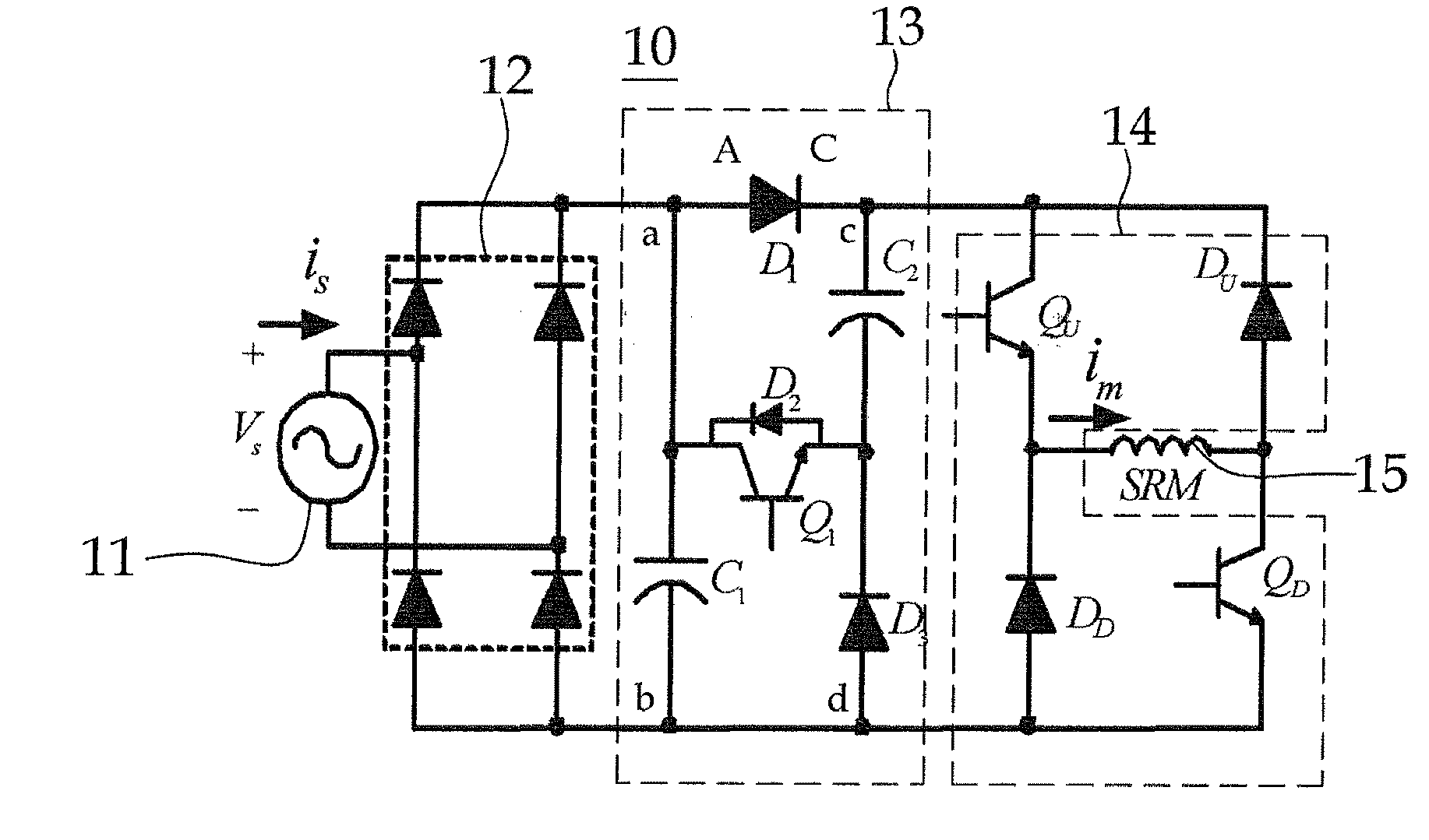
[0031]FIG. 2 is a circuit view showing the structure of the SRM driving apparatus according to the exemplary embodiment of the present invention.

[0032]In this embodiment, for example, the single-phase SRM driving apparatus, which drives an SRM by applying single-phase AC power, will be described.

[0033]The SRM driving apparatus 10 for driving an SRM 15 includes a power source 11 for supplying single-phase AC power, a rectifying module 12 including a bridge rectifying circuit to smooth the power supplied from the power source 11, a boost module 13 connected to the rectifying module 12, and a converter module 14 including an asymmetric bridge converter.

[0034]The boost module 13 includes first and second capacitors C1 and C2, first and third diodes D1 and D3, and an insulated gate bipolar transistor Q1...


PUM


Abstract

Disclosed is an active boost power converter for driving a single-phase SRM, capable of rapidly establishing excitation current in the excitation mode and reducing tail current and negative torque in the demagnetization mode under the high-speed operation of the SRM. The active boost power converter includes a boost module and a converter module connected to the boost module. The boost module includes first and second capacitors, first and second diodes and a switch device turned on/off to connect the first and second capacitors to each other in series or parallel. The switch device includes an insulated gate bipolar transistor (IGBT). The power converter is operated with first and second input modes and first and second output modes. Voltage of the first capacitor is equal to dc-link voltage and first and second capacitors are controlled to be operated in series or parallel by simply controlling the IGBT.

Description

BACKGROUND OF THE INVENTION[0001]1. Field of the Invention[0002]The present invention relates to an apparatus for driving a switched reluctance motor (hereinafter, referred to as SRM). More particularly, the present invention relates to an active boost power converter for driving a single-phase SRM, capable of improving the driving characteristic of the SRM upon the high-speed driving of the SRM.[0003]2. Description of the Related Art[0004]An SRM has been extensively used in various industrial fields due to the simple mechanical structure and the low manufacturing cost thereof. The SRM has the strong mechanical structure and can be operated in the wide speed range with the high output ratio, so the SRM can be operated at the high-speed.[0005]Meanwhile, a four-level converter has been suggested for the high-speed operation of the SRM.[0006]FIGS. 1A to 1D are circuit views showing the operation modes of a four-level converter employed in a conventional SRM driving apparatus.[0007]Refe...

Claims


Application Information

Patent Timeline
IPC IPC(8): H02M7/06
CPCY02B70/126H02M1/4208Y02B70/10H02M3/28
Inventor LIANG, JIANINGAHN, JIN WOOLEE, DONG HEE
Owner KYUNGPOOK NAT UNIV IND ACADEMIC COOP FOUND
Why Eureka
Try Eureka