System for underwater compressed fluid energy storage and method of deploying same

a compressed fluid and energy storage technology, applied in sea energy generation, artificial islands, construction, etc., can solve the problems of limited locations viable for their use, inability to fully exploit the resources of re sources, and inability to meet the needs of users, etc., to achieve efficient and cost-effective effects

Inactive Publication Date: 2011-03-24
BRIGHT ENERGY STORAGE TECHNOLOGIES LLP
View PDF64 Cites 48 Cited by
  • Summary
  • Abstract
  • Description
  • Claims
  • Application Information

AI Technical Summary

Benefits of technology

[0010]Therefore, it would be desirable to design an apparatus and method of storing and recovering energy in a compressed fluid energy stora

Problems solved by technology

However, RE sources are often not fully exploited because many forms of renewable energy are not available when the peak demand is present.
For instance, RE sources may be most available during undesirable off-peak hours, or may be located in areas that are remote from population centers or locations where power is most needed, having to share the grid during peak hours along with all the other peak power sources.
Geothermal and OTEC are also good baseload RE resources; however, locations viable for their use tend to be limited.
However these sources tend to be intermittent in their ability to provide power.
For instance, wind energy may be cost effective on a cost per kWh but does not may not produce energy when it's needed.
It faces impediments to even modest grid penetration levels largely due to the timing of its power output, which is not only not dispatchable according to the demands of the grid, but it varies uncontrollably according to wind levels.
This problem will get worse as more RE sources of all kinds are added to the grid—as long as cost effective storage is unavailable.
Above 20% renewable energy fraction, electrical power grids often lose stability without energy storage to modulate energy supply and demand.
Cost-effective storage for the electrical grid has been sought from the beginning of electrical service delivery but is not yet available.
The variation in power demand throughout a day, and season-to-season, requires having generation assets that are utilized only part of the time, which can

Method used


Image

  • System for underwater compressed fluid energy storage and method of deploying same
  • System for underwater compressed fluid energy storage and method of deploying same
  • System for underwater compressed fluid energy storage and method of deploying same

Examples


Embodiment Construction

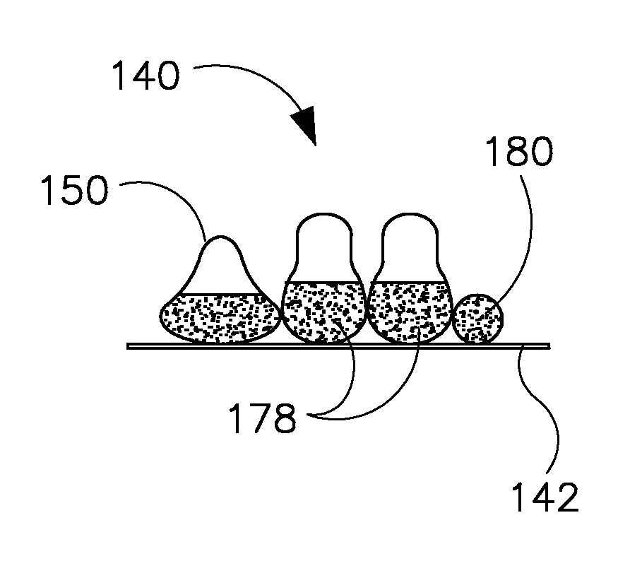
[0032]Embodiments of the invention include deployment or installation of compressed fluid storage vessels on a floor of an ocean, sea, lake, reservoir, gulf, harbor, inlet, river, or any other manmade or natural body of water. As used herein, “sea” refers to any such body of water, and “sea floor” refers to the floor thereof. “Fluid,” as used herein, refers to any compressible gas or liquid such as air, CO2, or the like as well as to a supercritical fluid. “Sediment” (e.g., “sea floor sediment”), as used herein, refers to marine material from the bottom or sea floor of the sea and may include, by way of example, gravel, sand, silt, clay, mud, organic or other material settled onto the floor of the sea.

[0033]In disclosed embodiments of the system, compressed fluid is stored in a bag in (or referred to as ‘under’) a body of water. Hydrostatic pressure of surrounding water becomes the predominant restraining parameter for the compressed fluid, which is pressurized into the bag via a co...


PUM


Abstract

A system and method for underwater compressed fluid energy storage include a compressed fluid storage system that comprises a fluid containment vessel positioned on a floor of a body of water, wherein the fluid containment vessel comprises sediment positioned therein to ballast the vessel on the floor.

Description

CROSS-REFERENCE TO RELATED APPLICATION[0001]The present application claims priority to U.S. Provisional Application 61 / 245,279 filed Sep. 23, 2009, to U.S. Provisional Application 61 / 309,415 filed Mar. 1, 2010, to U.S. Provisional Application 61 / 364,364 filed Jul. 14, 2010, and to U.S. Provisional Application 61 / 364,368 filed Jul. 14, 2010, the disclosures of which are incorporated herein.BACKGROUND OF THE INVENTION[0002]Embodiments of the invention relate generally to compressed fluid energy storage and, more particularly, to a method and apparatus of storing compressed fluid in an underwater storage device and extracting energy therefrom. In embodiments where the fluid compressed is air, such inventions are part of a class of energy storage systems known as compressed air energy storage (CAES) systems, but in this document we will use CAES to refer generically to any compressed fluid energy storage system.[0003]Renewable energy (RE) sources offer an alternative to conventional pow...

Claims


Application Information

Patent Timeline
IPC IPC(8): E02D29/00
CPCE02D29/10Y02E60/17Y02E10/38Y02E10/30Y02E60/16
Inventor FRAZIER, SCOTT RAYMONDVON HERZEN, BRIAN
Owner BRIGHT ENERGY STORAGE TECHNOLOGIES LLP
Why Eureka
Try Eureka