Self drilling rock bolting

a self-drilling, rock bolting technology, applied in the direction of anchoring bolts, earthwork drilling and mining, mining structures, etc., can solve the problems of slow bolt installation cycle time, time-consuming operation, and system also suffers from time-consuming

Inactive Publication Date: 2011-03-24
ALMINCO
View PDF2 Cites 50 Cited by
  • Summary
  • Abstract
  • Description
  • Claims
  • Application Information

AI Technical Summary

Benefits of technology

[0010]In use water, resin and catalyst are pumped through respective conduits at selected times, and enter a channel in the rock bolt. Mixing of the catalyst and the resin only occurs after they have entered the rock bolt, and as a result there is reduced risk of the drilling apparatus becoming blocked with prematurely hardened resin.
[0011]The system may further comprise a hydraulically driven pump to pump water to a first fluid inlet. It may also comprise pumps to pump resin and catalyst to second and third fluid inlets. The pumps may operate to provide different resin and catalyst flow rates. In addition they may provide precise differential control, to allow different resin catalyst mix ratios for different bolting conditions.

Problems solved by technology

A disadvantage with the above described bolting method is that it is a multi stage, and is thus time consuming operation.
The complicated nature of this bolting installation technique also requires significant manual handling, which results in slow bolt installation cycle times.
Accordingly, this system also suffers from being time consuming.
A disadvantage with this system is that the resin capsule may prematurely rupture during transportation, or during the boring process, prior to completion of the boring process.
A further disadvantage is that the bolts have a limited shelf life on account of the expiration of the resin capsule.
A disadvantage this type of system is that the bolt is grouted in a secondary process, requiring the use of grouting equipment that is separate from the drilling equipment.
This increases the installation cycle times and the labour required to install the bolts.

Method used


Image

  • Self drilling rock bolting
  • Self drilling rock bolting
  • Self drilling rock bolting

Examples


Embodiment Construction

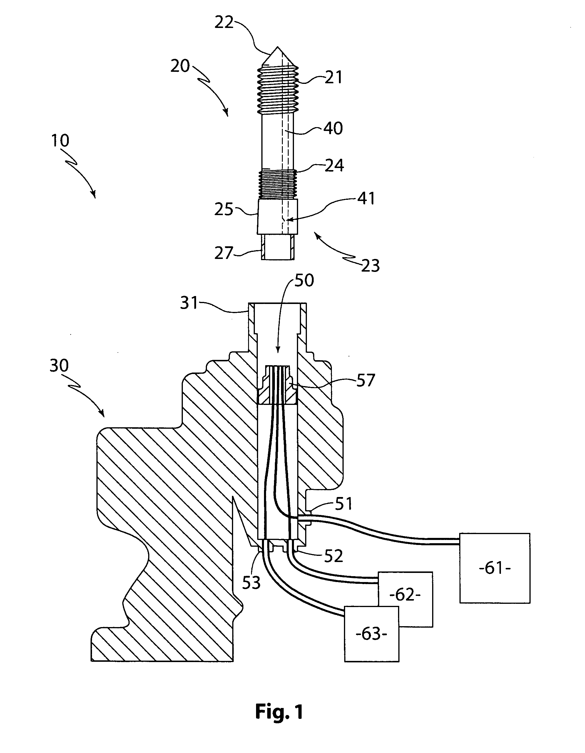
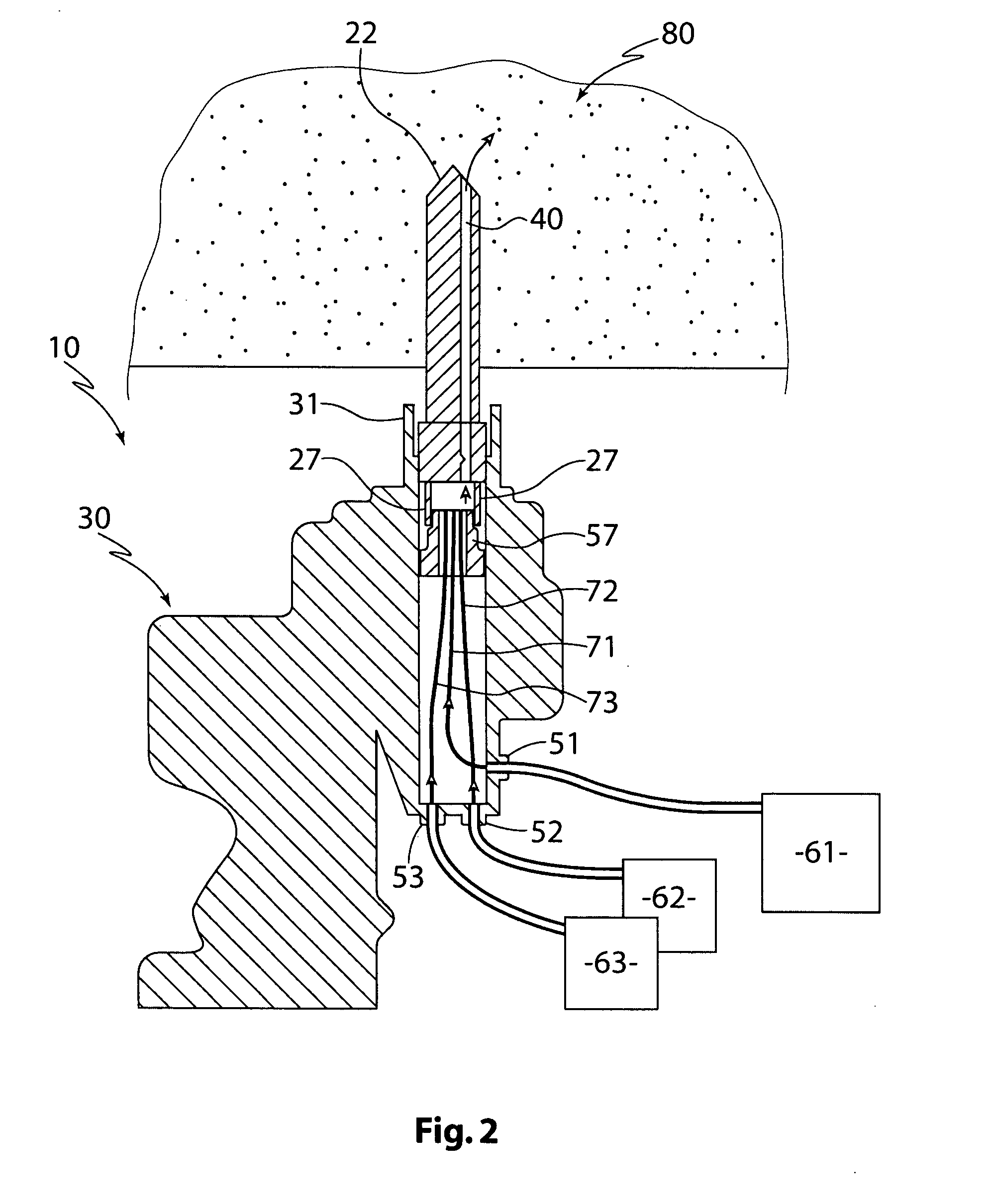
[0028]FIG. 1 depicts a rock bolt installation system 10 for securing a rock bolt 20 to a strata, such as a coal strata. The system 10 includes hydraulically operated drilling apparatus 30.

[0029]The drilling apparatus 30 is selectively operable in both clockwise and anticlockwise rotational directions.

[0030]The rock bolt 20 has a leading end 21 with a cutting tip 22 and a trailing end 23. The leading end 21 is threaded and has a coarse pitch. Part of the trailing end 23 is also threaded but has a fine pitch 24. The trailing end 23 of the rock bolt 20 also includes a fixed collar 27. A nut 25 is threadingly engageable with the fine pitch 24 of the rock bolt above the collar 27. The nut 25 which has a polygonal profile that mates with the chuck 31 of drill 30.

[0031]When the nut 25 is rotated toward the trailing end 23, it comes into abutment with the collar 27, as shown in FIG. 1. This abutment prevents the nut 25 from moving further toward the trailing end 23.

[0032]The rock bolt 20 ha...


PUM


Abstract

The present invention relates to self drilling rock bolting. In particular, the invention concerns both a drilling apparatus for rock bolting, and a rock bolt for use with the drilling apparatus. The drilling apparatus comprises within it a fluid injector having an upper part that mates with a self-drilling rock bolt for boring a hole. The injector includes three fluid inlets, three fluid outlets in the upper part, and three fluid conduits extending from respective inlets to respective outlets. The self drilling rock bolt comprises an elongate body having a leading end with a cutting tip, and around the tip a thread with a coarse pitch. The bolt also has a trailing end with an integral collar for fluid connection to a channel that extends axially through the body of the rock bolt to the leading end. Above the collar is a thread with a fine pitch. In other aspects the invention concerns a system comprising the drilling apparatus in combination with a rock bolt and a method for rock bolting using the system. The invention has application, but not exclusively, to rock bolting to stabilise the roof and walls of underground coal mines.

Description

FIELD OF THE INVENTION[0001]The present invention relates to self drilling rock bolting. In particular, the invention concerns both a drilling apparatus for rock bolting, and a rock bolt for use with the drilling apparatus. In other aspects the invention concerns a system comprising the drilling apparatus in combination with a rock bolt and a method for rock bolting using the system. The invention has application, but not exclusively, to rock bolting to stabilise the roof and walls of underground coal mines.BACKGROUND OF THE INVENTION[0002]Self drilling rock bolts are known for providing a single drilling and securing function. This negates the need to drill a hole, withdraw the drill bit and subsequently insert a bolt into the hole.[0003]An existing method of securing a rock bolt to a coal strata is to drill a hole in the coal strata using a drill mast with a drill bit attached thereto. After the hole has been bored and the drill bit retracted, the drill bit is removed from the dri...

Claims


Application Information

Patent Timeline
Patent Type & Authority Applications(United States)
IPC IPC(8): E21D21/00
CPCE21D20/02E21D2021/0053E21D20/028E21D21/0053
Inventor RICARDO, DI PIETRO
Owner ALMINCO
Why Eureka
Try Eureka