Frictional drive device and inverted pendulum type vehicle using the same

a technology of friction drive and inverter, which is applied in the direction of battery/cell propulsion, transportation and packaging, etc., can solve the problems of low efficiency of transmission power from the drive assembly to the main wheel, and the inability of the annular member and the drive disk to coaxially assemble, etc., and achieve high drive efficiency

Inactive Publication Date: 2011-03-24
HONDA MOTOR CO LTD
View PDF10 Cites 33 Cited by
  • Summary
  • Abstract
  • Description
  • Claims
  • Application Information

AI Technical Summary

Benefits of technology

[0004]In view of such problems of the prior art, a primary object of the present invention is to provide a frictional drive device having the above discussed structure and a vehicle using the same that allow a relatively large number of driven rollers to be engaged by the drive rollers and hence enables a relative high drive efficiency to be maintained even when the axial center of the annular member and the axial center of the drive disks are offset from each other.
[0006]Because the spring members urge the drive rollers against the driven rollers via the roller brackets, even when the central axial lines of the drive disks and annular member are offset from each other, a relatively large number of the drive rollers can keep engaging the driven rollers. Thereby, a high drive efficiency can be maintained, and a relatively high torque can be transmitted without incurring slippage.
[0008]According to a preferred embodiment of the present invention, the device further comprises a roller bracket rotatably supporting each drive roller, and a peripheral part of each drive disk is provided with a plurality of recesses, each roller bracket being received in the corresponding recess with the spring member interposed between bottom surfaces of the roller bracket and recess. Thereby, each roller bracket can be slidably received in each recess and positively guided in a prescribed direction while resiliently urged by the spring member so that a relatively large displacement of each roller bracket and hence each drive roller can be accommodated.

Problems solved by technology

However, according to this previously proposed inverted pendulum type vehicle, because the main wheel is simply held between the two drive assemblies, and no arrangement is made to positively position the main wheel with respect to the drive disks, the annular member and drive disks may not be coaxially disposed.
Therefore, only a small portion of the drive rollers are allowed to engage the driven rollers, and the efficiency of transmitting power from the drive assemblies to the main wheel may not be high.

Method used


Image

  • Frictional drive device and inverted pendulum type vehicle using the same
  • Frictional drive device and inverted pendulum type vehicle using the same
  • Frictional drive device and inverted pendulum type vehicle using the same

Examples


first embodiment

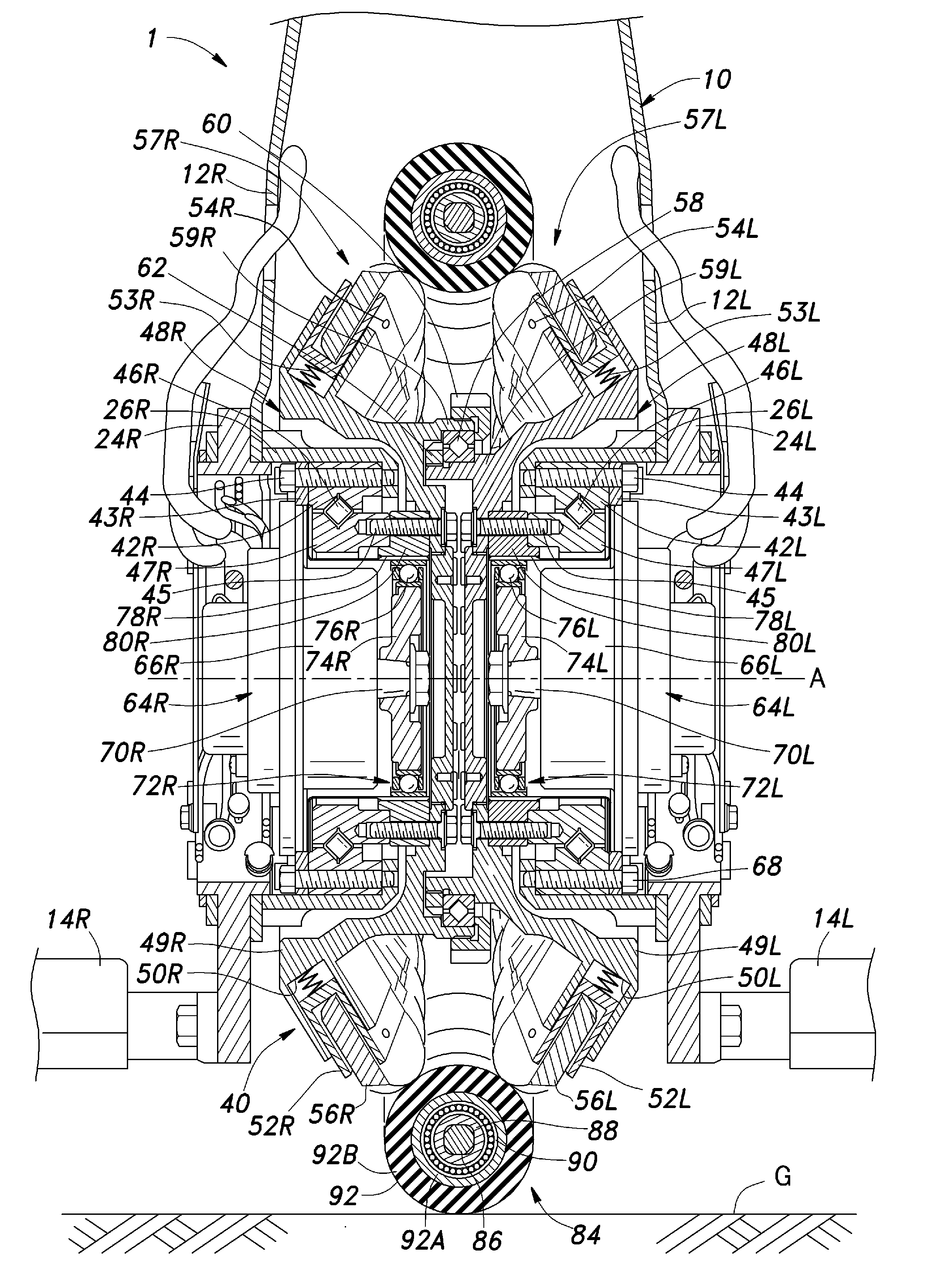
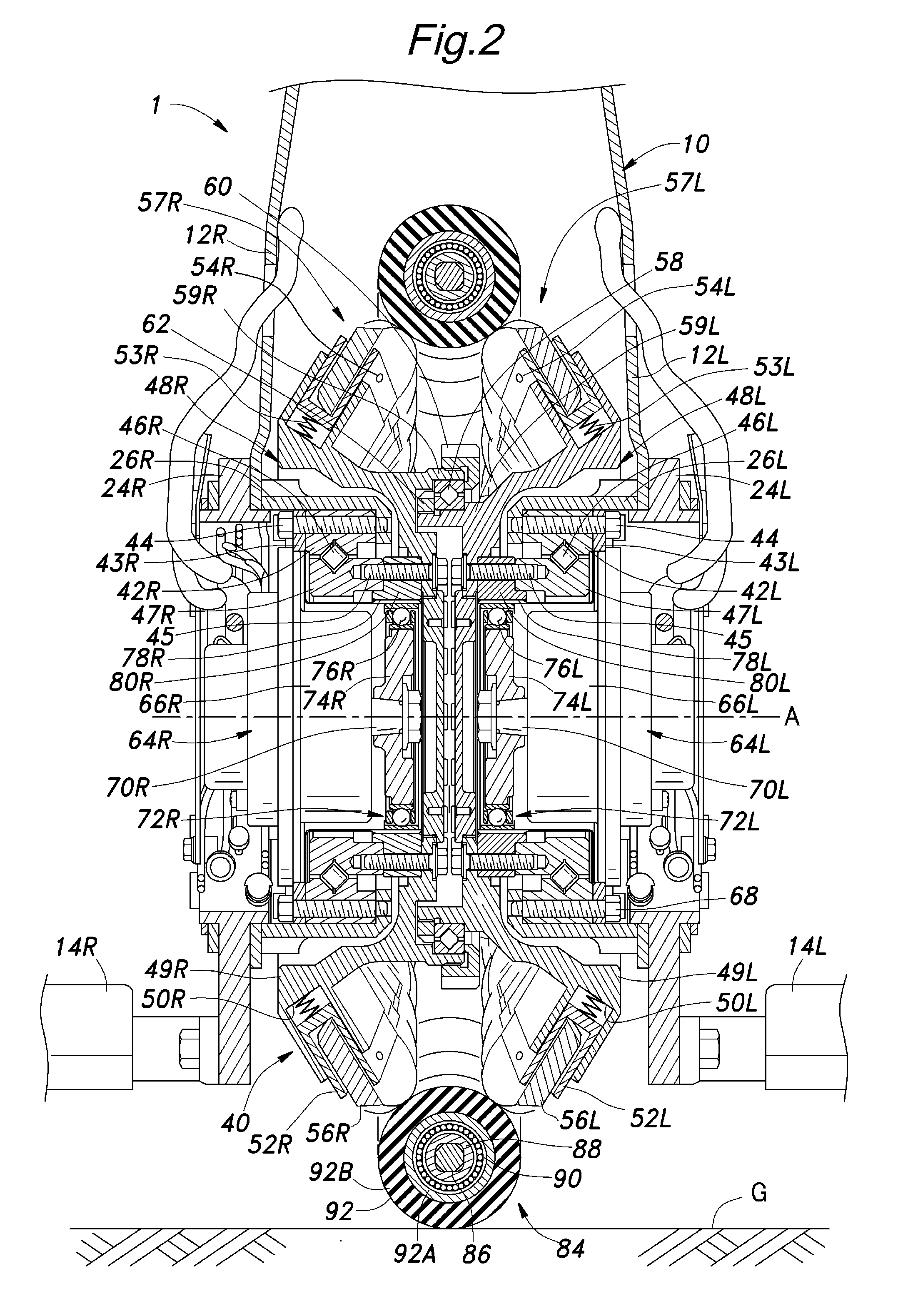
[0042]The annular member 111 of the main wheel 110 is given with an elasticity that allows the main wheel 110 to be deformed into an elliptic or track shape when the load of the vehicle 1 (the weight of the vehicle and vehicle occupant or rider) is applied to the main wheel 110 via the guide roller 120. Similarly as the first embodiment, the annular member 111 rotatably supports a plurality of driven rollers 92 each via an inner sleeve 99 and a ball bearing 90.

[0043]The guide roller 120 is given with an hourglass shape having a middle part of a reduced diameter so as to engage the main wheel 110 over a large contact area. The guide roller 120 engage those driven rollers 92 located in an upper part of the main wheel 110 so that these driven rollers 92 are forced into contact with the corresponding drive rollers 56 of the two drive disks 48. In other words, those driven rollers 92 located in the upper part of the main wheel 110 are held between those drive rollers 56 located in the up...

second embodiment

[0045]In the second embodiment, the distance between the driven rollers 92 and drive rollers 56 is relatively large in the front and rear parts of the drive disks 48. However, as the drive rollers 56 are supported by the roller bracket 52 which are resiliently retained by the corresponding drive disks 48, the drive rollers 56 can maintain the engagement with the driven rollers 92 over the entire periphery of the main wheel 84.

[0046]FIG. 6 shows a third embodiment or a modification of the second embodiment. Instead of compressing the main wheel 110 between the upper guide roller 120 and floor surface G as in the second embodiment, a front guide roller 125 engages a front part of the main wheel 110 and a rear guide roller 126 engages a rear part of the main wheel 110 both in the direction to stretch the main wheel 110 in the fore and aft direction into an elongated elliptic or track shape. In this case, those drive rollers 56 located ahead and behind the drive disks 48 do not engage t...


PUM

PropertyMeasurementUnit
resiliencyaaaaaaaaaa
pressureaaaaaaaaaa
circumferenceaaaaaaaaaa

Abstract

In a frictional drive device comprising a pair of drive disks (48) rotatably supported by a frame (10) around a central axial line (A) in a mutually opposing relationship, a pair of motors (64) supported by the frame for individually rotatively actuating the drive disks, a plurality of drive rollers (56) arranged along an outer periphery of each drive disk at a regular interval and each having a rotational center line so as to be rotatable along a plane which is neither parallel nor perpendicular to the central axial line, and an annular main wheel (84, 110) disposed approximately coaxially with respect to the central axial line and engaged by the drive rollers of the drive disks, the main wheel comprising an annular member (86, 111) and a plurality of driven rollers (92) supported along the annular member so as to be rotatable around a tangential line of the annular member, a resiliency is incorporated either in the main wheel or in the drive rollers so that a relatively large number of driven rollers can be simultaneously engaged by the drive rollers and, hence, a relative high drive efficiency can be maintained even when the axial center of the annular member and the axial center of the drive disks are offset from each other.

Description

TECHNICAL FIELD[0001]The present invention relates to a frictional rive device and an inverted pendulum type vehicle using the same.BACKGROUND OF THE INVENTION[0002]Known is an inverted pendulum type vehicle or an omni-directional vehicle comprising a pair of drive assemblies individually actuated by electric motors and a main wheel held between the drive assemblies and frictionally driven by the drive assemblies. See WO2008132779A1(US20100096905A1) for instance. Each drive assembly comprises a drive disk coaxially opposing the drive disk of the other drive assembly and a plurality of drive rollers obliquely arranged along the circumference of the drive disk at a regular interval so as to be individually rotatable. The main wheel comprises a ring-shaped annular member rotatably supported by a frame around a central axial line thereof and a plurality of driven rollers arranged along the circumference of the annular member so as to be rotatable around the respective tangential lines. ...

Claims


Application Information

Patent Timeline
Patent Type & Authority Applications(United States)
IPC IPC(8): F16H13/02
CPCB60B9/06B60B9/10B60B19/003B60B19/125B60B2200/47B60B2900/131B60B2310/56B60B2360/10B60B2360/50B60B2380/12B60B2310/305B60L50/52Y02T10/70Y02T10/64
Inventor GOMI, HIROSHITAKENAKA, TORUKUWABARA, KAZUYA
Owner HONDA MOTOR CO LTD
Why Eureka
Try Eureka