Riser top structure for circulating fluidized bed gasification furnace

a technology of fluidized bed and circulating fluid, which is applied in the direction of combustible gas production, combustion types, lighting and heating apparatus, etc., can solve the problems of lack of heat necessary for gasification of raw materials, insufficient heating of circulation medium, and deterioration of combustion quality, so as to enhance the flow velocity and enhance the flow velocity of combustion gas

Active Publication Date: 2011-03-31
IHI CORP
View PDF4 Cites 6 Cited by
  • Summary
  • Abstract
  • Description
  • Claims
  • Application Information

AI Technical Summary

Benefits of technology

[0019]According to a riser top structure for a circulating fluidized bed gasification furnace of the invention, a lateral duct for interconnecting a riser top and a cyclone separator comprises an introduction portion at connection with the riser having a cross-sectional area equal to that of the riser and a throttled portion between the introduction portion and the cyclone separator having a cross-sectional area gradually reduced from the introduction portion to the cyclone separator to enhance a flow velocity of the combustion gas, so that the circulation medium blown up to an upper end of the riser is smoothly guided into the introduction portion of the lateral duct having the cross-sectional area equal to that of the riser. The circulation medium once introduced into the introduction portion is guided to the cyclone separator without dropping into the riser, with an advantageous effect that an amount of the circulation medium circulated to the fluidized bed gasification furnace is substantially increased. The combustion gas introduced into the introduction portion is enhanced in flow velocity by the throttled portion, with an advantageous result that the circulation medium is favorably captured by the cyclone separator.

Problems solved by technology

However, a given reaction time is required for combustion of char in the riser 1; mere enhancement of the superficial velocity in the riser 1 by increase of the air amount would bring about deteriorated combustion quality, possibly resulting in the insufficiently heated circulation medium.
Such failure of the increased circulation medium 5 from the riser 1 to the fluidized bed gasification furnace 7 may result in lack of heat necessary for gasification of the raw material 8 in the fluidized bed gasification furnace 7.
As a result, disadvantageously, running or equipment cost will increase.

Method used


Image

  • Riser top structure for circulating fluidized bed gasification furnace
  • Riser top structure for circulating fluidized bed gasification furnace
  • Riser top structure for circulating fluidized bed gasification furnace

Examples


Embodiment Construction

[0028]Embodiments of the invention will be described in conjunction with the attached drawings.

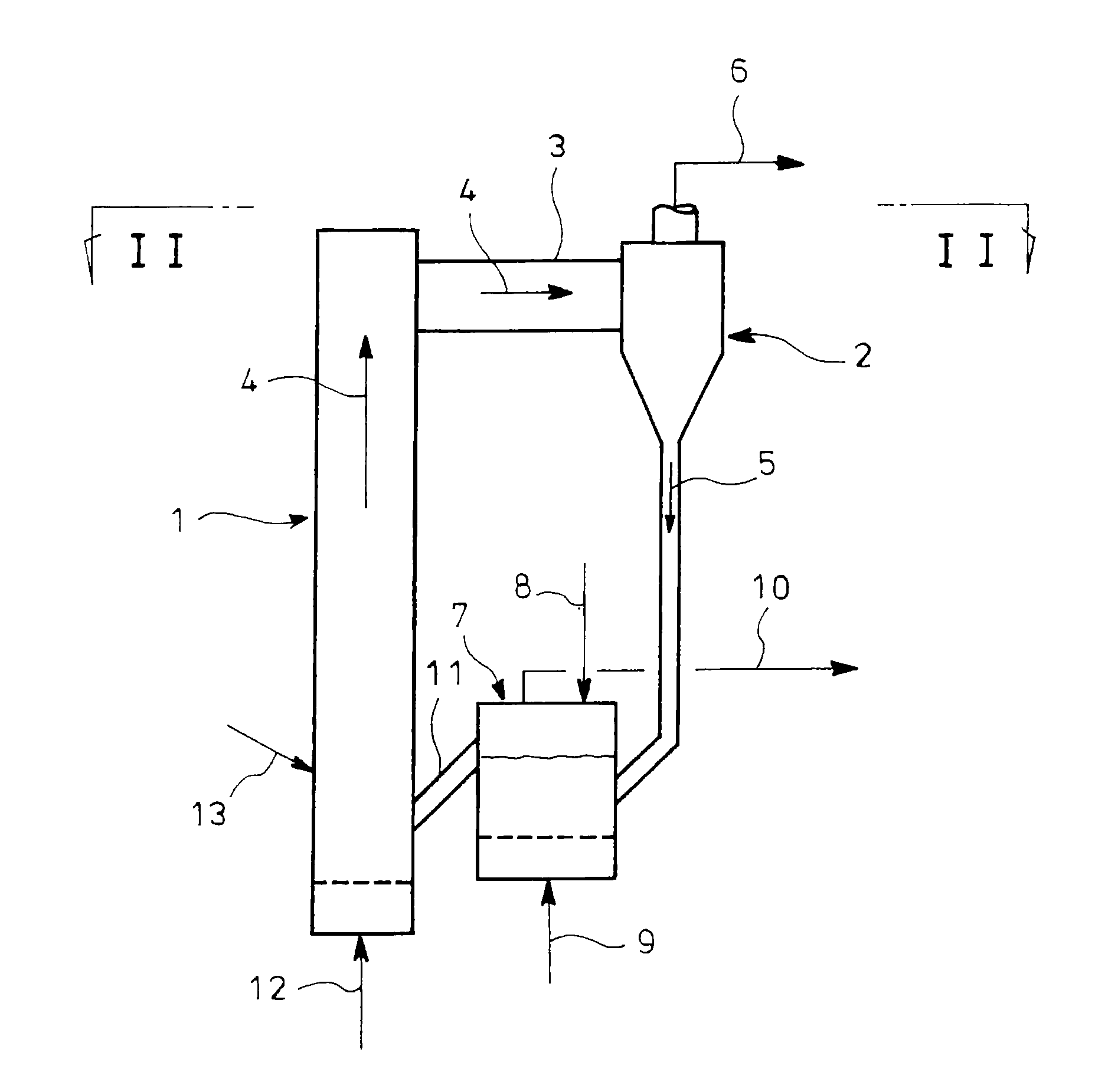
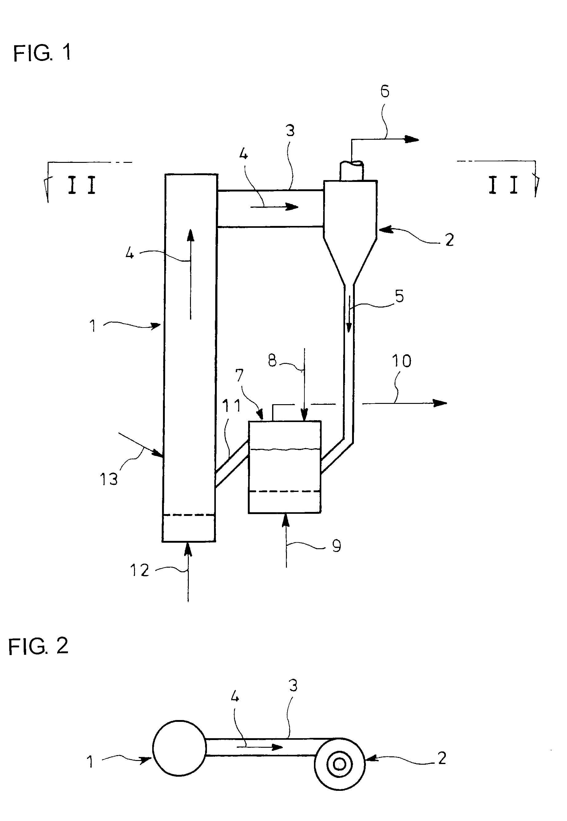
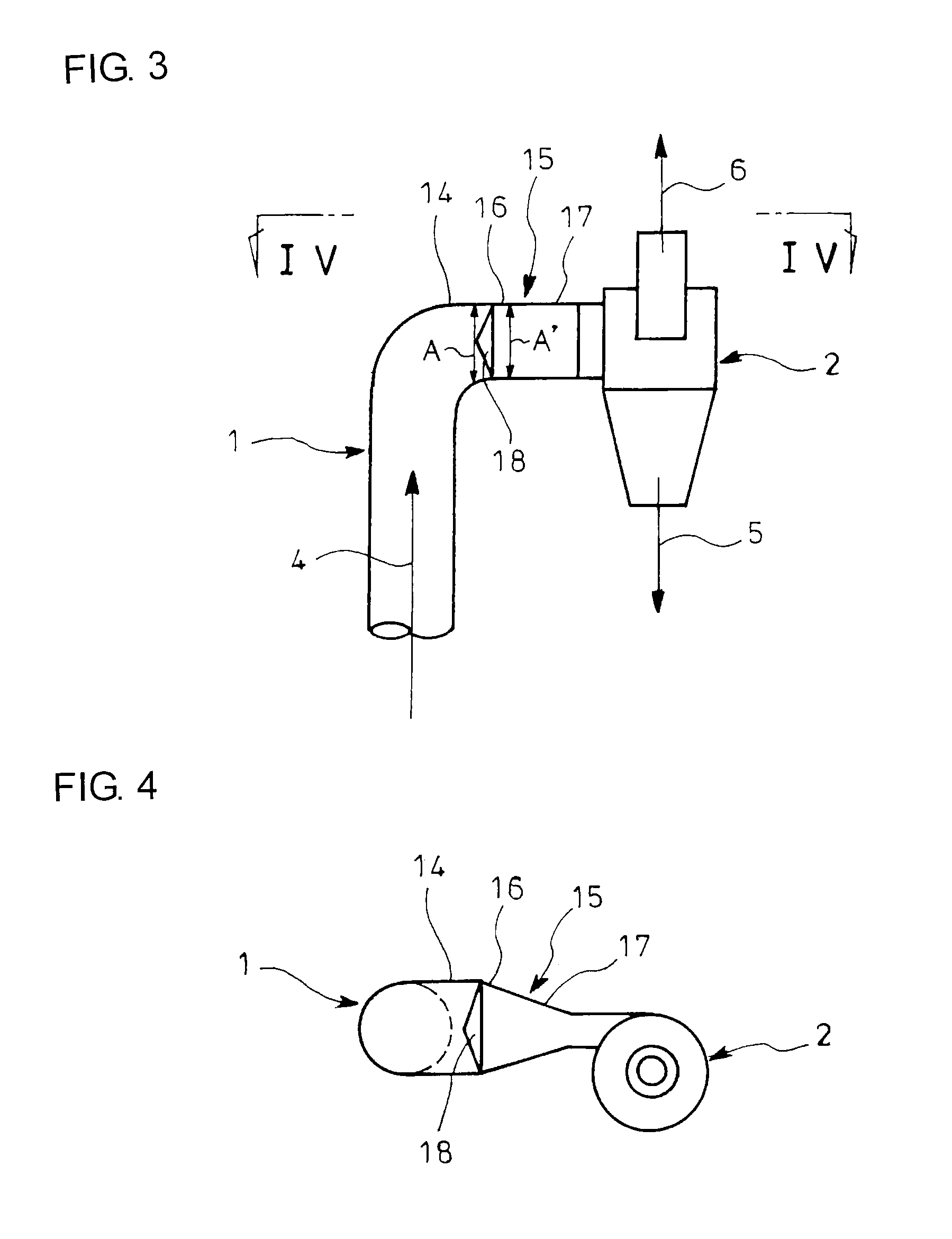
[0029]FIG. 3 is a front view showing an embodiment of the invention applied to a riser top for a circulating fluidized bed gasification furnace shown in FIGS. 1 and 2, and FIG. 4 is a plan view looking in the direction of arrows IV in FIG. 3. In FIGS. 3 and 4, parts similar to those in FIGS. 1 and 2 are represented by the same reference numerals. As shown in FIGS. 3 and 4, an upper end of a cylindrical riser 1 is formed with a curved portion 14 which has a cross-sectional area equal to that of the riser 1 and which is bent laterally to a cyclone separator 2, an end of the curved portion 14 being connected to the cyclone separator 2 through a lateral duct 15 having varied cross section.

[0030]The lateral duct 15 comprises an introduction portion 16 which has a cross-sectional area A′ equal to a cross-sectional area A of the curved portion 14 and which is connected in rectangular cross sectio...


PUM


Abstract

A lateral duct 15 for interconnecting a riser 1 and a cyclone separator 2 has an introduction portion 16 at the connection with the riser 1 which has a cross-sectional area equal to that of the riser 1, and a throttled portion 17 between the introduction portion 16 and the cyclone separator 2 which has cross-sectional areas gradually reduced from the introduction portion 16 to the cyclone separator 2 so as to increase a flow velocity of combustion gas.

Description

TECHNICAL FIELD[0001]The present invention relates to a riser top structure for a circulating fluidized bed gasification furnace which can increase in a simple construction an amount of circulation medium taken out from a riser to thereby increase a circulated amount of circulation medium.BACKGROUND ART[0002]There is a conventional circulating fluidized bed furnace wherein circulation medium is heated by combustion in a riser (a fluidized combustion furnace) and combustion gas blown up is laterally introduced through a lateral duct into a cyclone separator for capture of the circulation medium, the captured circulation medium being guided to and stored in a storage. The stored circulation medium is fluidized for circulation into the riser (see Patent Literature 1).[0003]In Patent Literature 1, the fluidization of the circulation medium stored in the storage is controlled to control a flow rate of the circulation medium to be circulated to the riser. In Patent Literature 1, the amoun...

Claims


Application Information

Patent Timeline
Patent Type & Authority Applications(United States)
IPC IPC(8): F23K1/00
CPCF23C10/04F23C10/10F23C10/18F23C10/32C10J2300/1807C10J3/463C10J2300/0993C10J2300/1637F23C2206/102
Inventor TAKAFUJI, MAKOTOSUDA, TOSHIYUKI
Owner IHI CORP
Why Eureka
Try Eureka