Hybrid energy management system

Inactive Publication Date: 2011-03-31
CATERPILLAR INC
View PDF20 Cites 28 Cited by
  • Summary
  • Abstract
  • Description
  • Claims
  • Application Information

AI Technical Summary

Problems solved by technology

Moreover, the energy management system responsively estimates the net energy generated by the swing mechanism during the recovery period; limits the energy available for use from the energy storage device during the discharge period to the estimated net energy generated from the swing mechanism; and recharges the battery from the actual net energy generated during the recovery period.

Method used


Image

  • Hybrid energy management system
  • Hybrid energy management system
  • Hybrid energy management system

Examples


Embodiment Construction

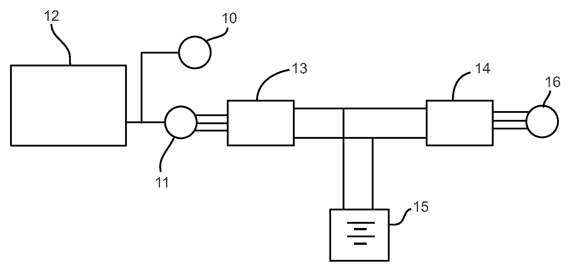
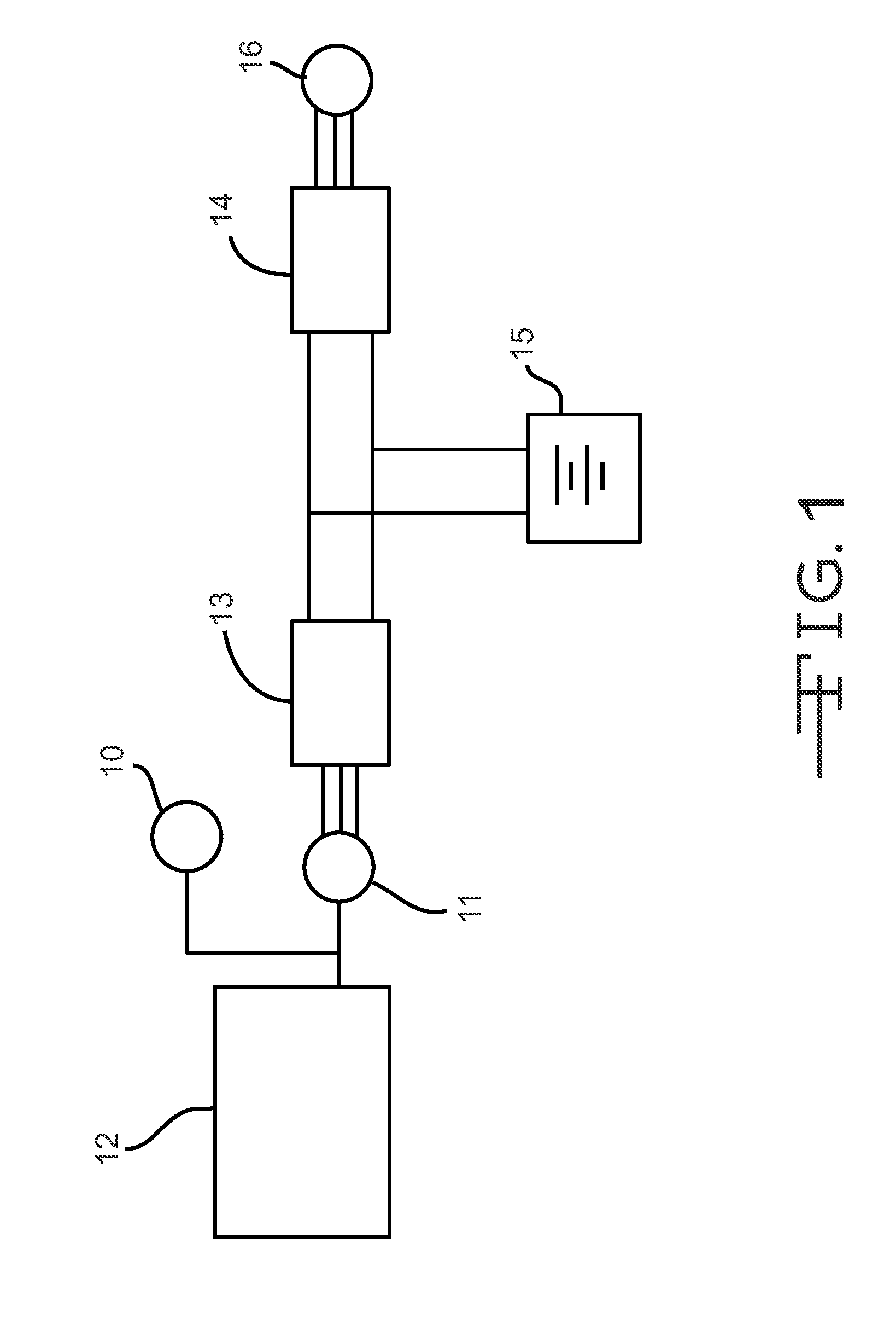
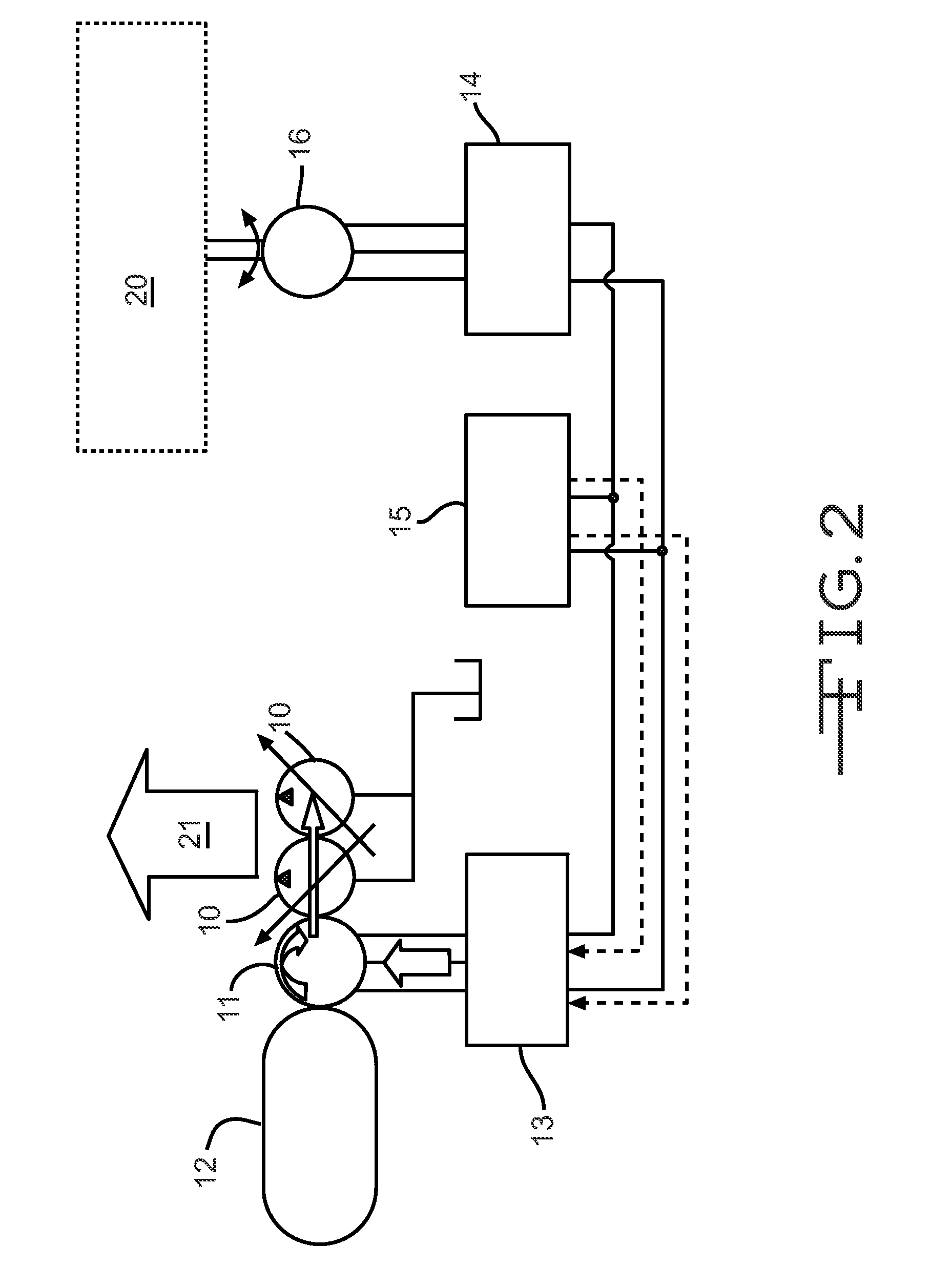
[0023]A hybrid energy management system has been designed such that it may recover and store energy from swing inertia during what is referred to herein as a recovery period. Further, as shown in FIG. 1, ESS 15 will provide electrical energy to drive an electric swing motor 16 during what is referred to herein as a discharge period, as well as for transient torque assist. To do so, the hybrid energy management system estimates the net regenerative energy that can be collected during the breaking action of the swing mechanism i.e., the recovery period. Since that equates to the net energy that can be used to recharge ESS 15 without using the engine 12, the hybrid energy management system regulates the amount of energy supplied by a motor / generator 11 such that the energy drawn from ESS 15 is limited to that net amount predicted to be available from the recovery period. The net regenerative energy is calculated by considering systemic inefficiencies, such as from motor 16 and inverter...


PUM


Abstract

A hybrid energy management system that estimates the net regenerative energy that can be collected during the breaking action of the swing mechanism, then, since this is the net energy that can be used to recharge an energy storage device without using the engine to help recharge the energy storage device, the system limits the use of the energy storage device to that net amount predicted to be available from the recovery period. The net regenerative energy is calculated by considering motor and inverter efficiencies for transferring energy to the battery and changes in the boom/stick/bucket inertia moment.

Description

RELATED APPLICATIONS[0001]This application is based upon and claims the benefit of priority from U.S. Provisional Application No. 61 / 245,848 by David L. Collins et al., filed Sep. 25, 2009, the contents of which are expressly incorporated herein by reference.TECHNICAL FIELD[0002]The present disclosure relates generally to a hybrid energy management system. More particularly, the present disclosure relates to a hybrid energy management system wherein the management system regulates the amount of overall energy available from an energy storage system during a discharge cycle to increase fuel efficiency and prolong energy storage system life.BACKGROUND[0003]As hybrid powertrains that include an energy storage device as part of an energy storage system (ESS), gain favor over conventional powertrains or hybrid powertrains that do not include such a device, energy management systems are being developed that will maximize overall fuel efficiency and prolong the life of said energy storage ...

Claims


Application Information

Patent Timeline
Patent Type & Authority Applications(United States)
IPC IPC(8): B60K6/42
CPCE02F9/2025Y02T10/84E02F9/2217E02F9/2075E02F9/123
Inventor COLLINS, DAVID L.TREICHEL, BENJAMIN A.POST, STEPHEN ERIC
Owner CATERPILLAR INC
Why Eureka
Try Eureka