Winding for a contact of a medium-voltage vacuum circuit-breaker with improved endurance, and an associated circuit-breaker or vacuum circuit-breaker, such as an ac generator disconnector circuit-breaker

a vacuum circuit breaker and medium-voltage technology, applied in the direction of contacts, high-tension/heavy-dress switches, electrical components, etc., can solve the problems of not being able to make copper slotted hollow cylinders, metal slitting sawing, and windings that do not allow slots, etc., to increase the mechanical endurance of a contact and large size

Active Publication Date: 2011-03-31
AREVA T&D
View PDF25 Cites 9 Cited by
  • Summary
  • Abstract
  • Description
  • Claims
  • Application Information

AI Technical Summary

Benefits of technology

[0031]The ANSI and CEI standards in effect for medium-voltage vacuum circuit-breakers are thus complied with. The slot widths reduced to below one millimeter avoid rupture of the turns during opening / closing cycles that cause strong impacts.
[0047]Thus, means are set in place within the brazing oven that enable both the distortion and the height of the winding to be controlled.
[0048]The main advantage of this method is that a winding of the invention is obtained that has a slot width that is less than one millimeter, without adding time to the duration of a cycle of the method of fabricating a contact, and without noticeably increasing the cost thereof.
[0049]In other words, the forming by compression at high-temperature enables the compression to be controlled and can be incorporated in the already-established method of fabricating vacuum circuit-breakers.
[0066]In an advantageous embodiment, the contact includes at least one stud distinct from the winding(s), and of an arrangement that is the subject matter of the patent application filed by the Applicant under the number FR 09 53853. The stud is thus arranged in the hollow of the first cylinder, as a spacer between the mechanical connection portion and the circular plate of the contact body in such a manner as to avoid the collapse thereof during a closing operation and in the closed position of the vacuum circuit-breaker, the stud(s) having high electrical resistance such that when a given current flows in the contact, the amount of current that flows in the stud(s) is negligible relative to the current that flows in the winding(s).

Problems solved by technology

The Applicant has observed that, when using existing technology, it is not practical to make copper slotted hollow cylinders with large diameters, typically lying in the range 90 mm and 150 mm, in order to achieve the desired magnetic field.
The machines for machining with metal slitting saws that are currently used for manufacturing windings do not allow slots to be made with a width of at least 1 mm.
However, with such slots, it is found that the drawbacks of large-diameter hollow cylinders and of vacuum circuit-breaker contacts incorporating such cylinders are numerous:
firstly, being intrinsically more fragile, the cylinders are more complicated to handle during contact production, to transport, and to store: and that may lead to them being distorted and / or may cause them to suffer variation in their height that is not desired;
This leads to a reduction in the mechanical endurance performance of large diameter contacts in a vacuum circuit-breaker that is incompatible with ANSI and CEI standards;
finally, the magnetic fields that need to be generated effectively for extinguishing an arc have proven to be inadequate for large diameter windings.
That solution proved undesirable because reducing the number of slots amounts to reducing the number of turns defined individually between two consecutive slots.
The addition of this shim, naturally leads to an increase in the cost of manufacturing the contact.
Further, with shim made from electrically insulating material, there is a great risk that particles of the material may become detached when the vacuum circuit-breaker is operated.
The detachment of such particles will inevitably damage the dielectric strength of the vacuum circuit-breaker.

Method used


Image

  • Winding for a contact of a medium-voltage vacuum circuit-breaker with improved endurance, and an associated circuit-breaker or vacuum circuit-breaker, such as an ac generator disconnector circuit-breaker
  • Winding for a contact of a medium-voltage vacuum circuit-breaker with improved endurance, and an associated circuit-breaker or vacuum circuit-breaker, such as an ac generator disconnector circuit-breaker
  • Winding for a contact of a medium-voltage vacuum circuit-breaker with improved endurance, and an associated circuit-breaker or vacuum circuit-breaker, such as an ac generator disconnector circuit-breaker

Examples


Embodiment Construction

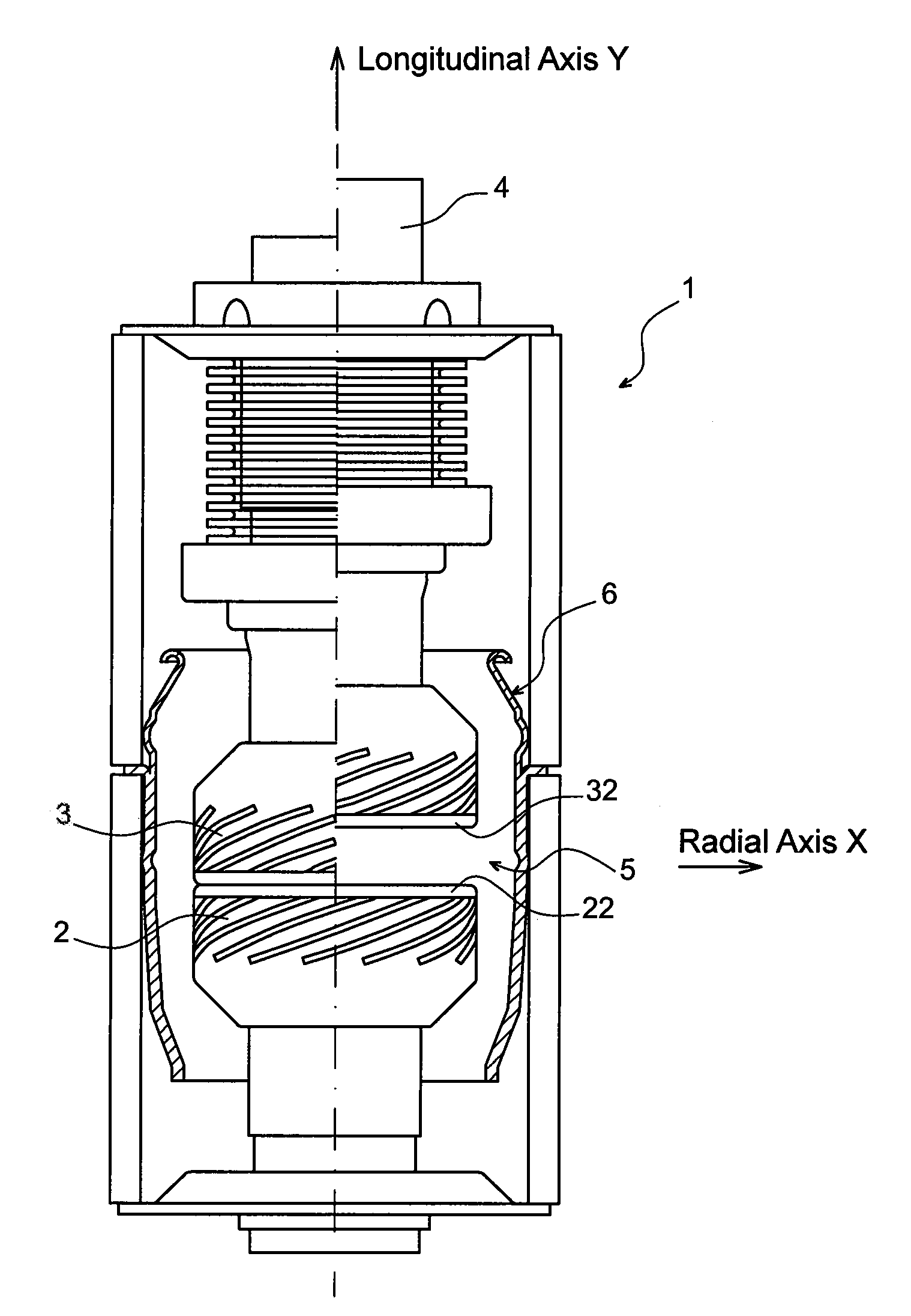
[0084]As shown in FIG. 1, a vacuum circuit-breaker 1 of the invention has a longitudinal axis Y and essentially includes a pair of contacts, of which one contact 2 is stationary and the other contact 3 is moved by an operating rod 4 between an open position (the portion shown on the right-hand side) and a closed position (the portion shown on the left-hand side). The contacts 2 and 3 are of large size (diameter >35 mm).

[0085]The contacts 2, 3 in a vacuum circuit-breaker are usually separated to extinguish an arc that is liable to be produced in the space 5 between these contacts

[0086]Whether in the closed position or the open position, the contacts 2, 3 are inside a shield 6 that is itself inside the jacket 7 of the circuit-breaker, within which there is a vacuum

[0087]Breaking high alternating currents requires the arc that is generated to be controlled.

[0088]The arc control means are usually an integral part of the vacuum circuit-breaker. They must therefore ensure that the energy ...


PUM

PropertyMeasurementUnit
diameteraaaaaaaaaa
diameteraaaaaaaaaa
widthaaaaaaaaaa

Abstract

A copper-based winding implementing a copper-based winding of diameter that is typically greater than 90 mm, designed to generate a magnetic field in an electrical contact for a medium-voltage vacuum circuit-breaker. The winding is constituted by a hollow cylinder including helical slots about its longitudinal axis and opening out both into the hollow and to the exterior of the cylinder, winding in which the space between two consecutive slots that form a turn is empty of material and the width of each initial slot is less than 1 mm.

Description

CROSS REFERENCE TO RELATED APPLICATIONS OR PRIORITY CLAIM[0001]This application claims priority of French Patent Application No. 09 53855, filed Jun. 10, 2009.TECHNICAL FIELD[0002]The invention relates to medium-voltage vacuum circuit-breakers, sometimes called vacuum bottles.[0003]It relates more particularly to improving the endurance of such vacuum circuit-breakers.[0004]The main application is that in which vacuum circuit-breakers are used as switches in alternating current (AC) generator disconnector circuit-breakers at the output of a power station.PRIOR ART[0005]Vacuum circuit-breakers have been used for very many years in medium-voltage electrical distribution switchgear to break short-circuit currents of the order of a few kiloamps (kA), typically 25 kA, at a few kilovolts (kV), typically 36 kV. In that type of distribution switchgear, vacuum circuit-breakers must also withstand the continuous current, typically of the order of 1250 amps (A), without overheating. The way th...

Claims


Application Information

Patent Timeline
Patent Type & Authority Applications(United States)
IPC IPC(8): H01H9/44H01H1/24H01F7/06
CPCY10T29/49071H01H33/6642
Inventor KANTAS, SAIDBERTHON, BRUNOTRIAIRE, CEDRIC
Owner AREVA T&D
Why Eureka
Try Eureka