Station For Disinfecting Publicly-Used Equipment

a technology for disinfecting public equipment and uv emitter stations, which is applied in the field of uv emitter stations, can solve the problems of insufficient power of known handheld uv emitters to conveniently disinfect public used equipment, insufficient effectiveness of each wipe, and inability to disinfect public use equipment. achieve the effect of uniform distribution of uv ligh

Active Publication Date: 2011-03-31
YORBA LINDA ENTERPRISES
View PDF15 Cites 21 Cited by
  • Summary
  • Abstract
  • Description
  • Claims
  • Application Information

AI Technical Summary

Benefits of technology

[0014]Irradiation is preferably performed by UV lamps, which are advantageously disposed to irradiate the equipment without significantly risking irradiation of customers or operations personnel. Two or more UV lamps are preferably disposed within the tunnel such that a majority of the external surfaces of the equipment are blanketed with the UV light or other radiation. The emitters are preferably oriented to maximize the exposure of equipment within the tunnel, while minimizing the exposure of persons or animals outside the tunnel. The UV lamps can extend along the walls of the housing, as well as the ceiling. It is preferred that at least one of the UV lamps provides an UV light intensity of at least 100 μW / cm2 of UV light at 1 meter from the UV lamp. In preferred embodiments, the lamps are distanced from the wall by at least 5 cm.
[0017]The housing can have at least first and second walls, with each wall having a plurality of reflective units. This is advantageous as the reflective units are each designed to direct the UV light from the UV lamps toward the equipment disposed within the tunnel to thereby provide a more uniform distribution of UV light on the equipment's surface.

Problems solved by technology

Surprisingly, existing UV emitter stations are impractical to disinfect publicly used equipment, despite the number of microorganisms that has been found to exist on surfaces including enteroccocus faecalis, escherichia coli, legionella pneumophila, legionella bozemanii, salmonella enteritidis, salmonela paratyphi (enteric fever), salmonella typhosa (typhoid fever), salmonella typhimurium, staphylococcus aerius, e. coli, and rotavirus.
For example, known handheld UV emitters have insufficient power to conveniently disinfect a shopping cart, let alone dozens of carts.
This is problematic as such dirty equipment exposes the public to harmful bacteria and other microorganisms.
However, each wipe is only minimally effective, and wipes are impractical for cleaning more than a small portion of a piece of equipment.
Although the Jones system could be useful in cleaning dirty carts, the system is disadvantageous for simply disinfecting carts because the many components have large energy requirements, and the overly complex system will likely lead to higher maintenance costs.
Although the Couvillion system reduces energy costs compared with the Jones system by using only a UV light source, the Couvillion device fails to sufficiently disinfect an entire cart due to the minimal UV light source mounted along the ceiling.
Although the devices apparently suffice in decontaminating the objects, the high number of UV lamps used will increase usage and maintenance costs of the device, and the V-shape configuration of the reflectors would likely be insufficient to disinfect a non-moving object.
However, the Cekic apparatus is configured to direct UV radiation to a planar surface at a set distance, and would likely be insufficient to irradiate non-planar surfaces at varying distances from the UV light source.

Method used


Image

  • Station For Disinfecting Publicly-Used Equipment
  • Station For Disinfecting Publicly-Used Equipment
  • Station For Disinfecting Publicly-Used Equipment

Examples


examples

[0069]The following examples illustrate particular embodiments of the present inventive subject matter, and aids those of skill in the art in understanding and practicing the inventive subject matter. It is set forth for explanatory purposes only, and is not to be taken as limiting the present inventive subject matter in any manner.

example # 1

Example #1

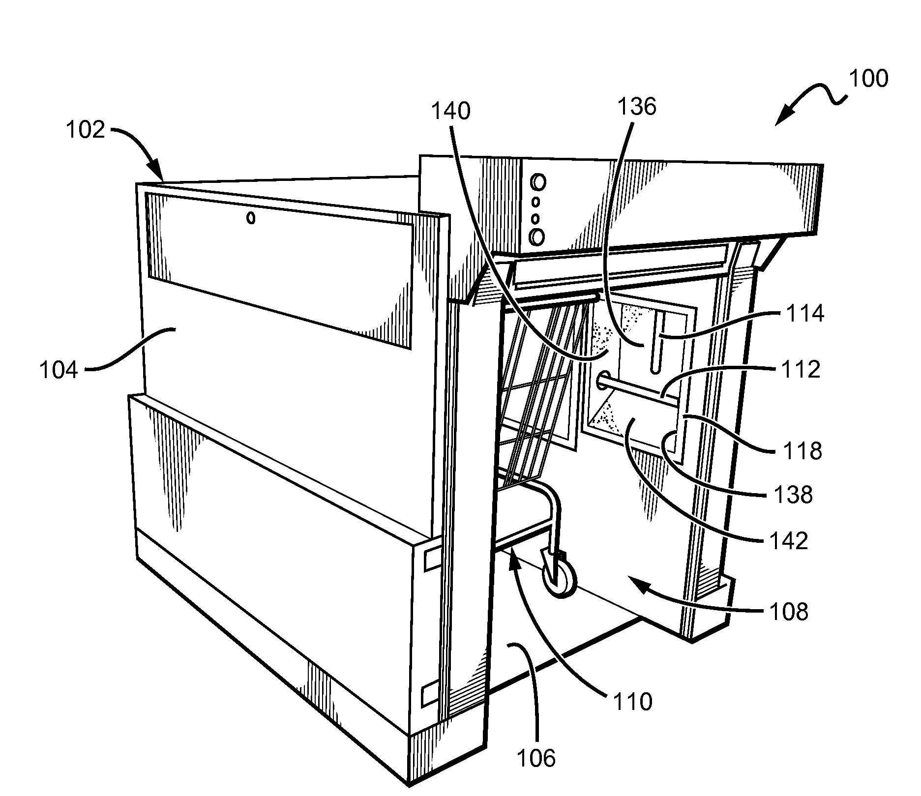
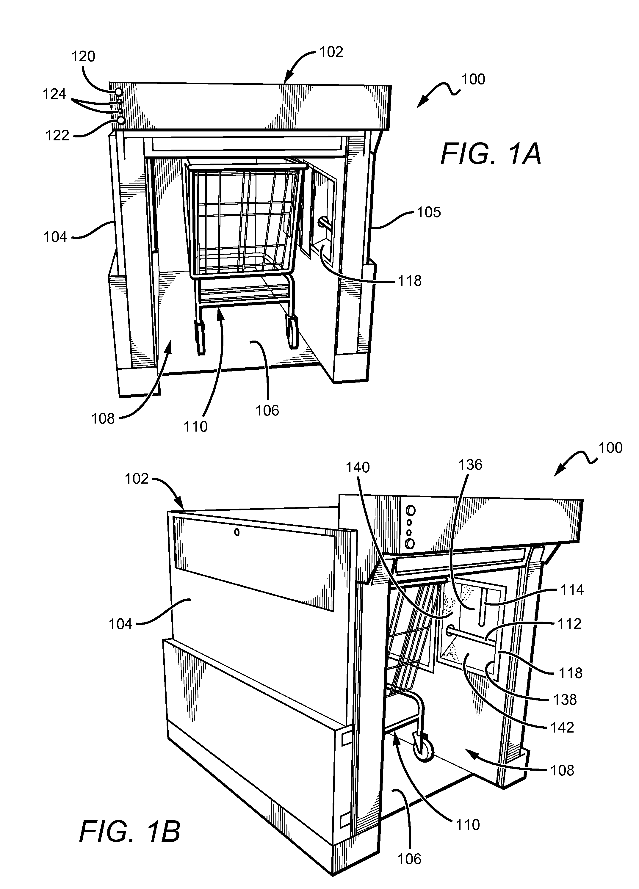
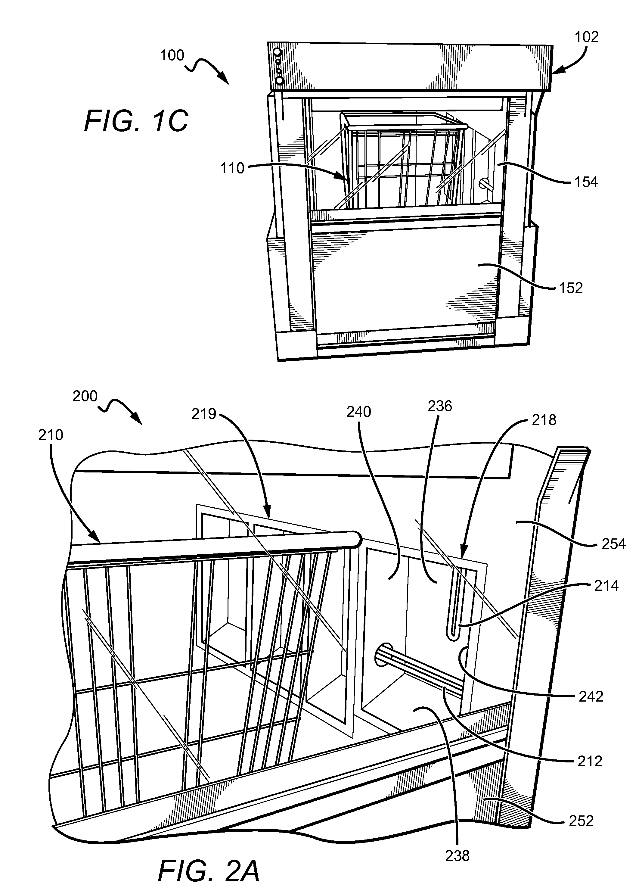
[0070]A device was tested having six UV bulbs disposed along the ceiling of the device. The UV bulbs produced UVc light at an intensity of 110 μWs / cm2 at a distance of 1 meter. The tunnel had a height of 48 in, a depth of 29 in, and a width of 45 in.

[0071]When the UV lamps were illuminated about the tunnel, the following intensities were found using a radiometer:

UV IntensityPortion of Shopping Cart Tested(μWs / cm2)Bottom of cart (17.5″ from floor) facing up at 5′ into unit208Bottom of cart (17.5″ from floor) facing up at 6′ into unit269Bottom of cart (17.5″ from floor) facing side of unit at37about 5′ into unitHandle bar of cart (42″ from floor) facing up at 5′ into unit128Handle bar of cart (42″ from floor) facing up at 6′ into unit694Top basket of cart (42″ from floor) facing side of unit at531about 5′ into unit

[0072]Based on the intensity measurements collected, inconsistency in the UV intensities at various areas of the shopping cart was discovered. In particular, the l...

example # 2

Example #2

[0073]A device was tested in which UV bulbs were disposed along the walls and ceiling of the device. The UV bulbs produced UVc light at an intensity of 110 μWs / cm2 at a distance of 1 meter. The tunnel had a height of 48 in, a depth of 29 in, and a width of 45 in.

[0074]When the UV lamps were illuminated about the tunnel, the following intensities were found using a radiometer:

UV IntensityPortion of Shopping Cart Tested(μWs / cm2)Bottom of cart (17.5″ from floor) facing upAbout 650Bottom of cart (17.5″ from floor) facing side of unitAbout 950Handle bar of cart (42″ from floor) facing upAbout 1500Top basket of cart (42″ from floor) facing upAbout 2800

[0075]Based on the intensity measurements collected, it is expected that much of the cart can be substantially disinfected of many of the common microorganisms in less than seven seconds of exposure. It is expected that the entire cart could be disinfected of many of the common microorganisms in about ten seconds.


PUM

PropertyMeasurementUnit
heightaaaaaaaaaa
heightaaaaaaaaaa
peak inactivation wavelengthaaaaaaaaaa

Abstract

A device for disinfecting publicly-used equipment includes a plurality of reflective units disposed along the interior of each wall of the device. Each of the reflective units can include a reflective back section and at least three reflective sections disposed about the reflective back section. UV lamps can be disposed to extend along the walls, and at partially disposed adjacent to a one or more reflective back sections of the reflective units. The UV lamps together with the reflective units collectively direct sufficient UV light on the equipment such that the equipment can be disinfected. The walls and ceiling of the device define a tunnel into which the equipment to be disinfected is inserted. Optionally, the device can include a door to prevent children and others from entering the tunnel while the UV lamps are illuminated.

Description

[0001]This application claims priority to our copending U.S. provisional application with the Ser. No. 61 / 247,361 which was filed Sep. 30, 2009, and which is incorporated by reference herein.FIELD OF THE INVENTION[0002]The field of the invention is disinfection devices.BACKGROUND[0003]It is known to utilize ultraviolet (“UV”) light to sterilize needles, catheters and other medical devices, to thereby reduce the risk of infection to patients. Such practice has also been applied to food, air, water, and other items, although in these other instances the effect is usually to disinfect rather than to sterilize. UV emitters can be stationary or portable, and can range in size from very large devices through which entire pallets of material can be processed, to small hand-held wands for home use.[0004]Surprisingly, existing UV emitter stations are impractical to disinfect publicly used equipment, despite the number of microorganisms that has been found to exist on surfaces including enter...

Claims


Application Information

Patent Timeline
Patent Type & Authority Applications(United States)
IPC IPC(8): A61L2/10
CPCA61L2/10A61L2202/14A61L2/24
Inventor TAYLOR, THOMAS L.HILT, PAT
Owner YORBA LINDA ENTERPRISES
Why Eureka
Try Eureka