Composite Liftgate System

a liftgate and composite technology, applied in the field of automobile liftgates, can solve the problems of high tooling cost, heavy weight of steel and smc liftgates, and styling restrictions with traditional sheet metal components, so as to improve styling flexibility, reduce tooling investment, and reduce the effect of system mass

Active Publication Date: 2011-03-31
MAGNA INTERNATIONAL INC
View PDF17 Cites 58 Cited by
  • Summary
  • Abstract
  • Description
  • Claims
  • Application Information

AI Technical Summary

Benefits of technology

[0007]The present invention is a thermoplastic composite liftgate system with reinforcements in key areas to allow the system to meet performance requirements, while lowering the tooling investment, lowering the system mass, and improving the styling flexibility. The present ivention includes an inner panel, and at least one bracket, or reinforcement, connected to the inner panel such that when a force is applied to the bracket, the force is distributed to the inner panel.

Problems solved by technology

Liftgates are traditionally made from stamped steel panels that are heavy and have a high tooling cost.
Steel and SMC liftgates have a mass penalty over thermoplastics.
There are also styling restrictions with traditional sheet metal components.
Thermoplastic composite type materials used for liftgate applications also have difficulty meeting customer performance specifications.
This will also add weight and increase manufacturing complexity as well.
This does not meet the higher load requirements desired in some applications, such as the latch pull test.

Method used


Image

  • Composite Liftgate System
  • Composite Liftgate System
  • Composite Liftgate System

Examples


Embodiment Construction

[0020]The following description of the preferred embodiment(s) is merely exemplary in nature and is in no way intended to limit the invention, its application, or uses.

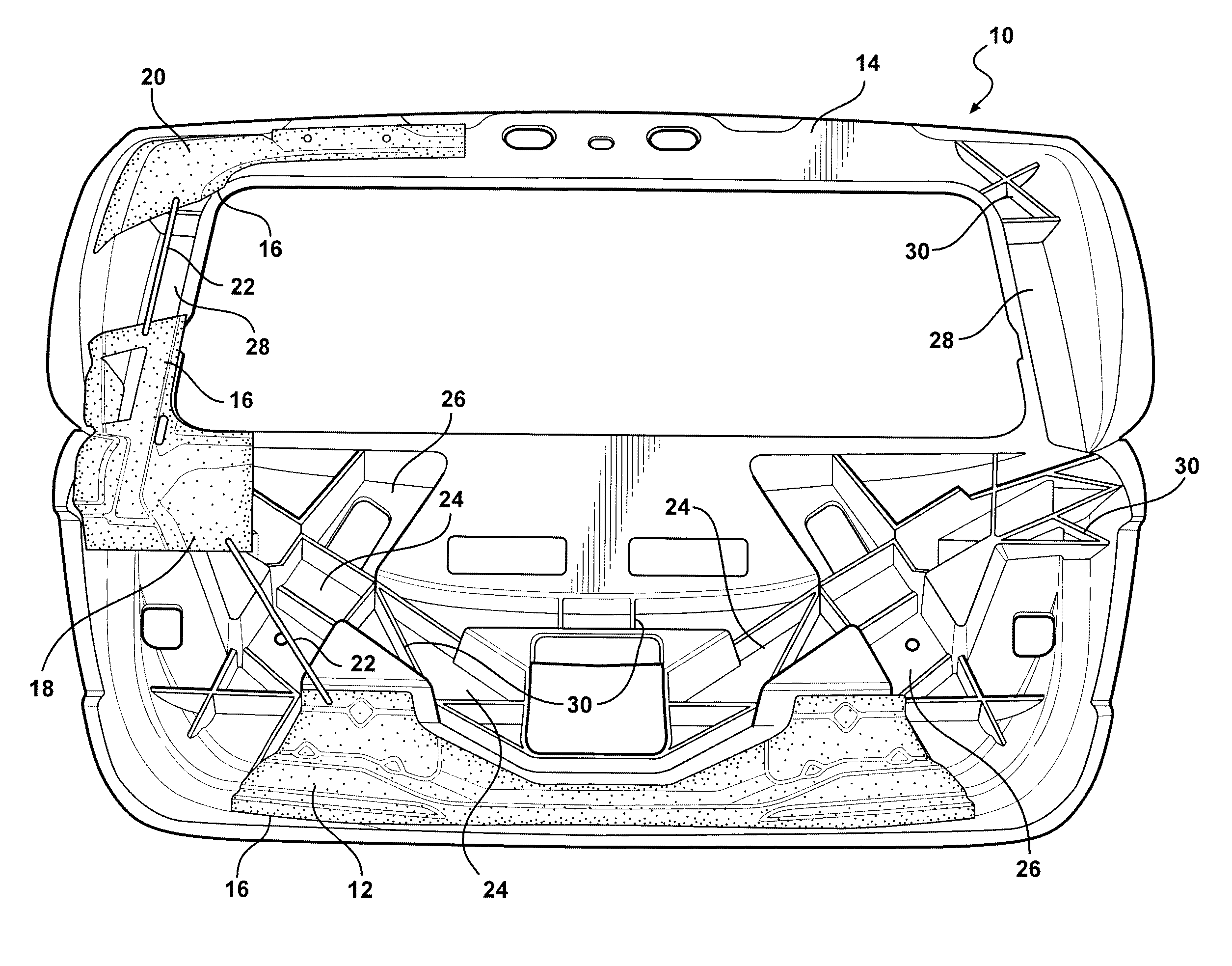
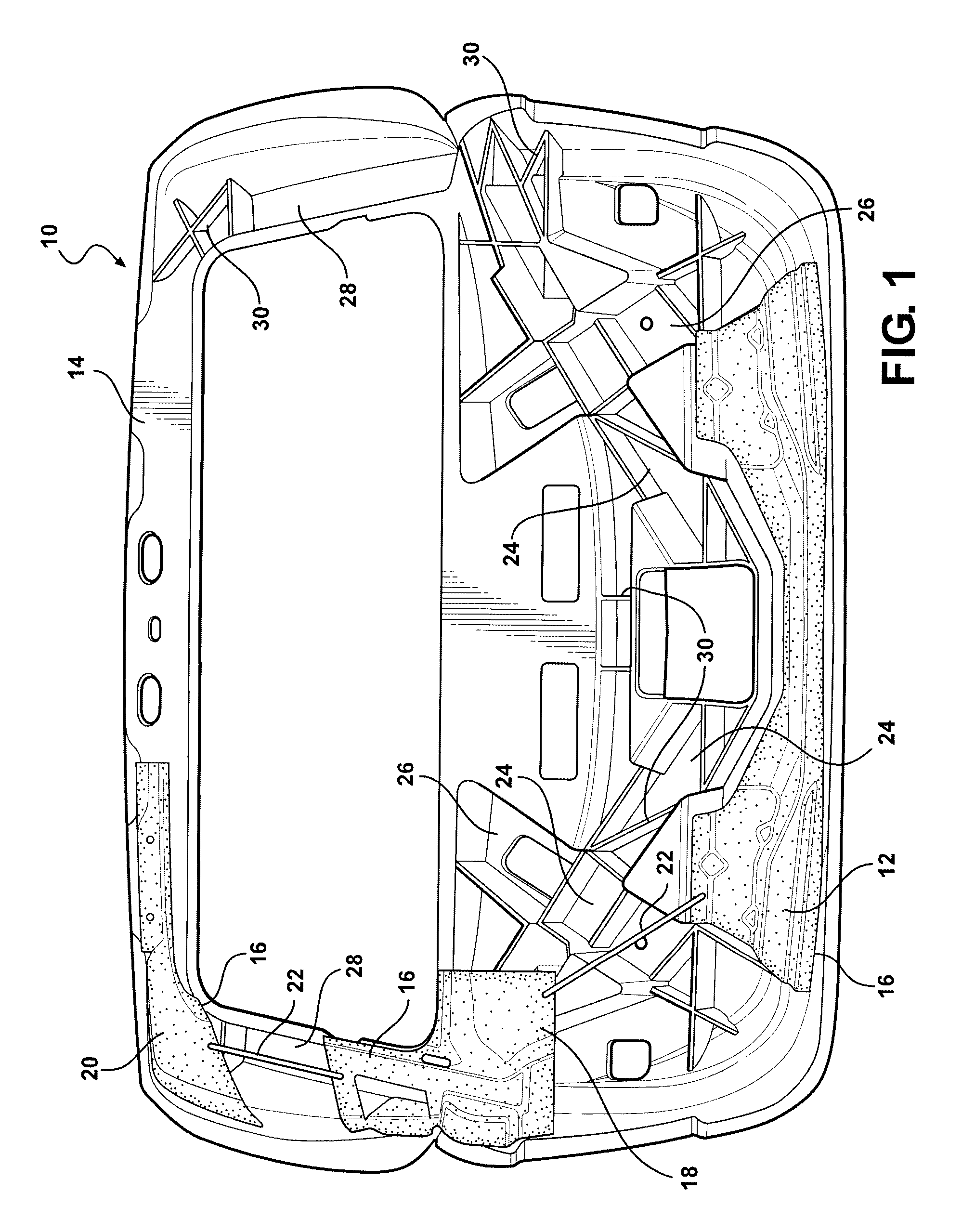
[0021]The composite liftgate system of the present invention utilizes a wide reinforcing bracket along with a latch which aids in spreading the load applied to the bracket over a larger area. The wide reinforcement bracket adds more structure by attaching to the inner panel with structural adhesive or insert molding. Additionally, the wide reinforcing bracket is also tied into other reinforcing brackets with steel tethers. The other reinforcing brackets are also connected to a hinge system through the use of additional steel tethers. The steel tethers are in the form of cables, stampings, tubes, etc., which reinforce the composite gate and the latch system (which ties to the body) to a counter balance system and the hinge system (which also ties back into the body structure).

[0022]The composite liftgate of the present...


PUM


Abstract

The present invention is a thermoplastic composite liftgate system with reinforcements in key areas to allow the system to meet performance requirements, while lowering the tooling investment, lowering the system mass, and improving the styling flexibility. The present invention includes an inner panel and at least one bracket or reinforcement member connected to the inner panel such that when a force is applied to the bracket, the force is distributed to the inner panel.

Description

CROSS-REFERENCE TO RELATED APPLICATIONS[0001]This application claims the benefit of U.S. Provisional Application No. 61 / 130,489, filed May 30, 2008. The disclosure of the above application is incorporated herein by reference.FIELD OF THE INVENTION[0002]The present invention relates to liftgates for automobiles. More specifically, the present invention relates to a composite liftgate for an automobile.BACKGROUND OF THE INVENTION[0003]One of the current trends in the automobile industry is to lower vehicle weight to help achieve better fuel economy, thus helping to meet fuel economy standards and to offset the higher fuel prices. Another trend is that there is a broader range of vehicle models, which in turn reduces the volume of vehicles produced on a per model basis. Liftgates are traditionally made from stamped steel panels that are heavy and have a high tooling cost. Sheet Molding Compound (SMC) is an alternative to steel for the inner and outer panels of the liftgate. Using SMC h...

Claims


Application Information

Patent Timeline
Patent Type & Authority Applications(United States)
IPC IPC(8): B60J5/10B62D29/04B62D33/027
CPCB60J5/107
Inventor KUNTZE, CHRISTOPHER JOHNRODDY, STEPHEN R.MCLEOD, MARTINVANBUSKIRK, MICHELLEKISELEV, ALEXANDERSCHALTE, GARI M.GUSCHEWSKI, NORMAN
Owner MAGNA INTERNATIONAL INC
Why Eureka
Try Eureka