Window mounted beam director

a beam director and window mount technology, applied in the direction of instruments, optical elements, weapons, etc., can solve the problems of inability to easily conceal, inability to deploy through the fuselage hole, and inability to meet the requirements of small aircraft,

Active Publication Date: 2011-03-31
THE BOEING CO
View PDF7 Cites 14 Cited by
  • Summary
  • Abstract
  • Description
  • Claims
  • Application Information

AI Technical Summary

Benefits of technology

[0010]In a second exemplary embodiment, a telescope mounted on a pantograph is employed. In a first configuration the pantograph employs a plurality of telescoping arms mounted to the weapon platform with ball joints as the outer steering assembly. The inner steering assembly has a telescope frame carried by the telescoping arms that rotationally supports a mounting hoop for first angular rotation of the telescope and engages an axial support for the telescope for second angular rotation of the telescope. The telescoping arms of the outer steering assembly provide multiple axis orthogonal positioning of the telescope frame for clearance of the telescope in rotational motion.

Problems solved by technology

The nose turret solution such as that adopted in the ABL occupies a location which is not feasible for many smaller aircraft for structural and aerodynamic reasons.
The solution employing deployment through a fuselage hole is unacceptable beyond a certain Mach number and cannot be concealed readily.
This would cause the size of the enclosing window to increase substantially.
The size of the laser window is a significant issue because highly specialized and costly glasses must be used to achieve the low adsorption level required to avoid excessive adsorption in, and heating of, the window as well as excessive distortion of the laser beam.
Extremely large pieces of such glasses are extremely costly or may require development of larger vacuum furnaces for fabrication and polishing.
The complex curvature in the window is in itself a source of distortion of the laser beam and degradation in the performance of the laser system.
All of these issues become more critical and complex where there are special surface treatment requirements for the aircraft such as stealth capability.

Method used


Image

  • Window mounted beam director
  • Window mounted beam director
  • Window mounted beam director

Examples


Embodiment Construction

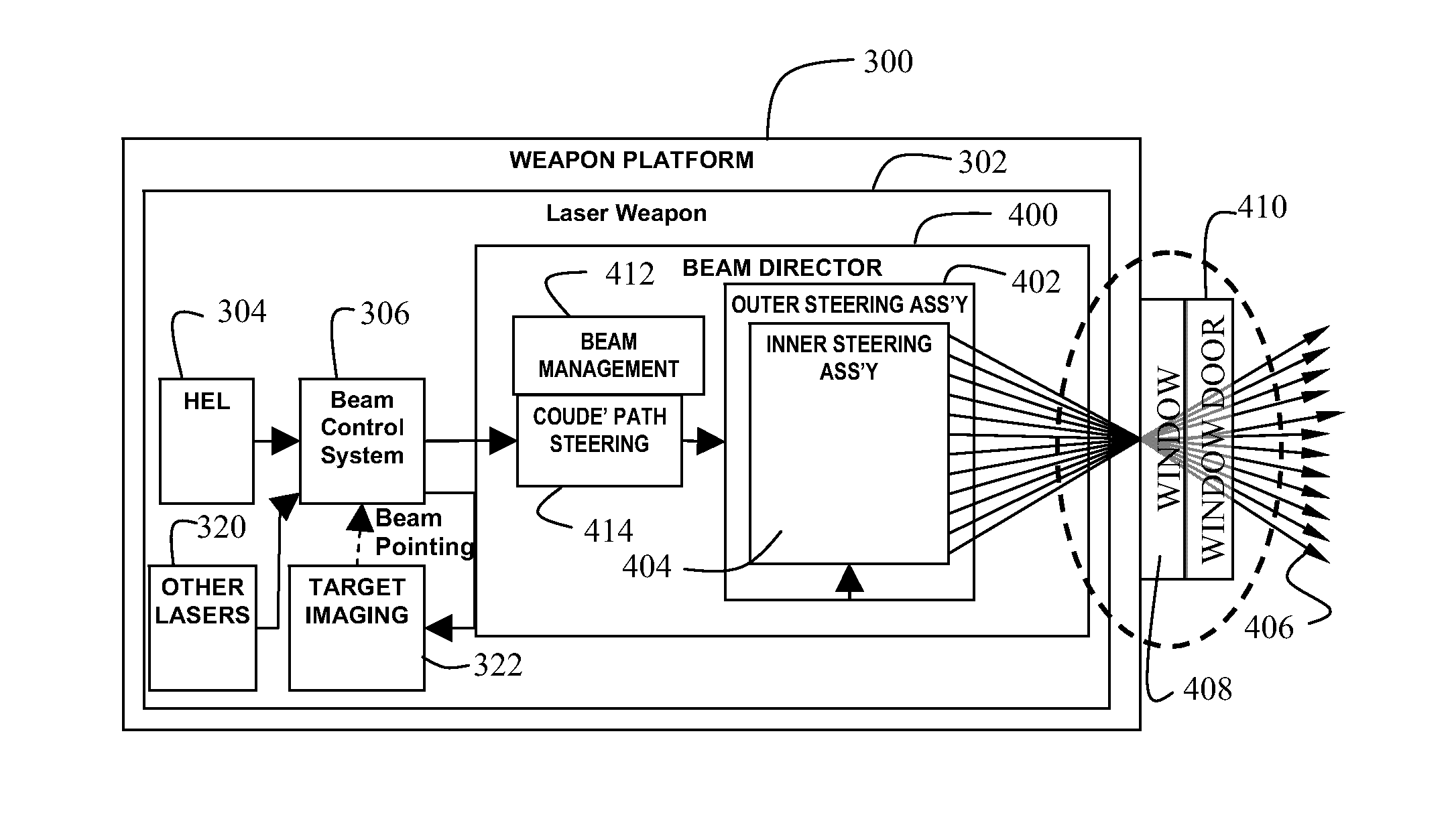
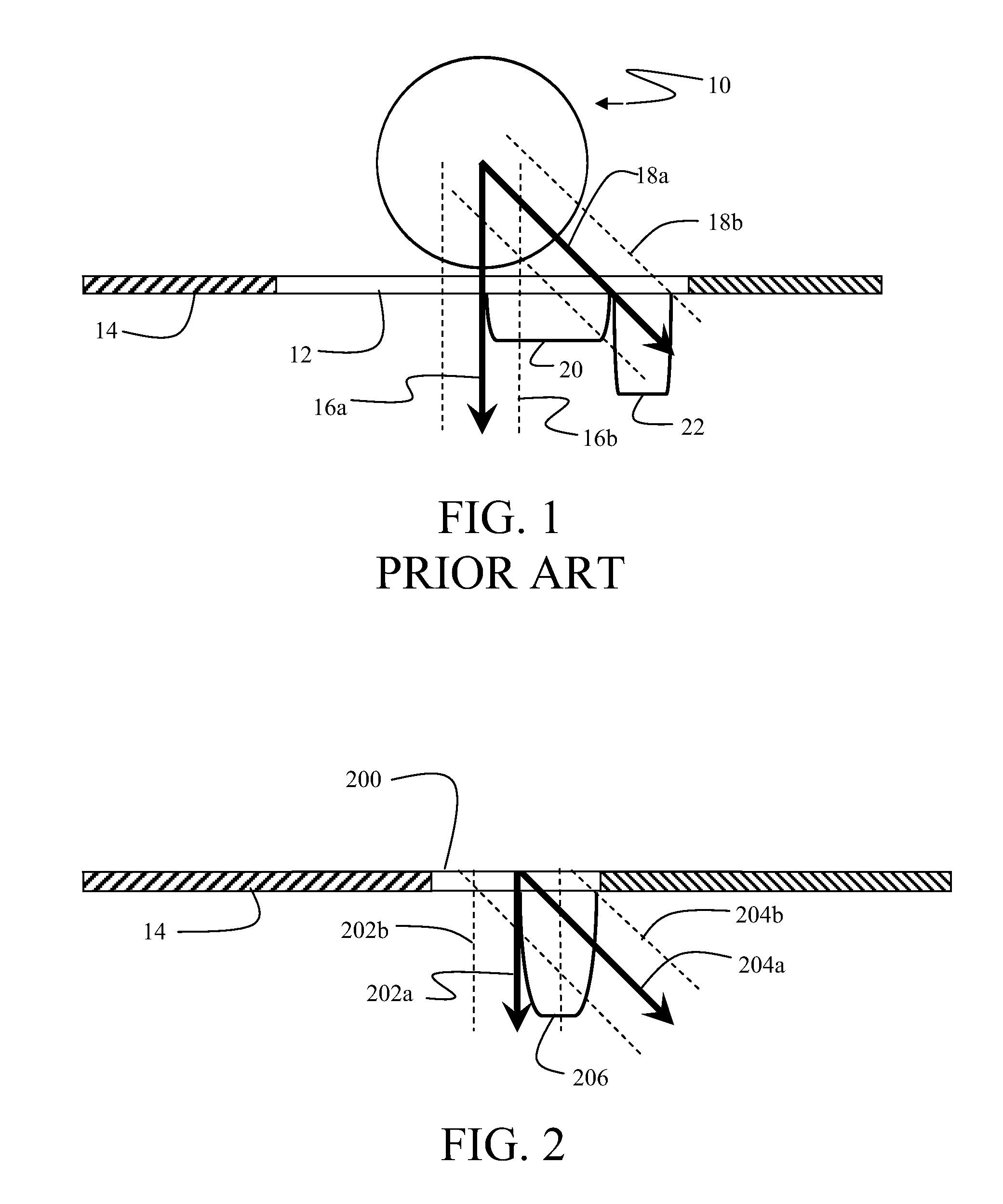
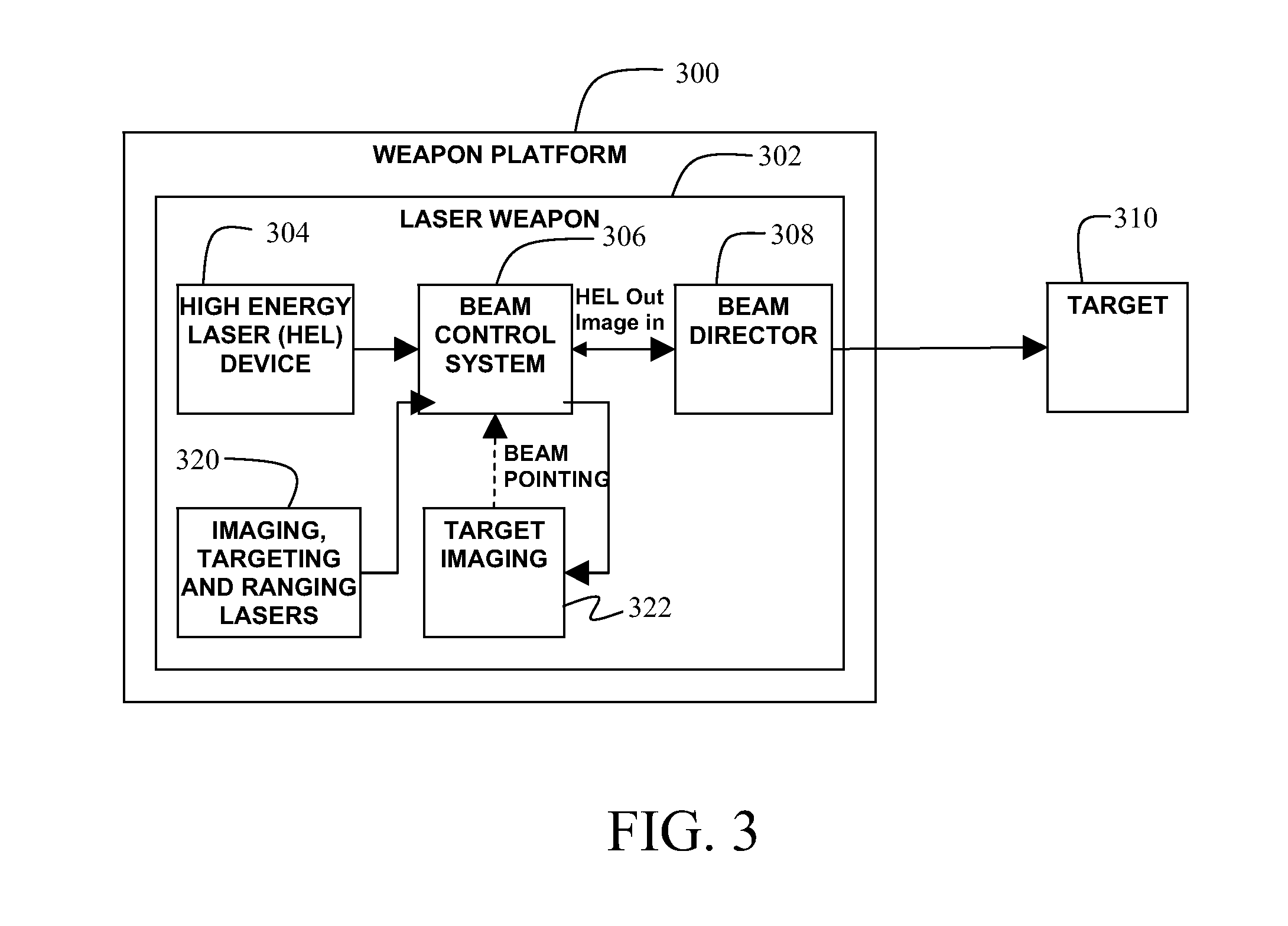
[0024]The embodiments described herein demonstrate a beam director integrated with a window which maintains the laser beam center at the same or substantially the same location on the enclosing window irrespective of the orientation at which the laser is projected. FIG. 1 shows a prior art beam director 10 mounted behind a window 12 in an aircraft structure 14. Such a conventional beam director (ball turret) located behind a window slews the beam across the window as the turret steers the beam. The direction of the beam shown with a first perpendicular aspect centerline 16a with a beam half-width 16b to a second angled aspect centerline 18a with a beam half-width 18b requires that the window have sufficient dimensions to accommodate the lateral displacement 20 of beam centerline impingement on the window for the desired field of regard (FOR) for the beam director and the additional width 22 required by the beam half-width 18b required by the beam angulation. FIG. 2 shows an exemplar...


PUM


Abstract

A laser system employs a window integrated in the surface of a weapon platform. A high energy laser is mounted in the weapon platform to provide a laser beam which is received by a Coude' path for internal direction of the beam. A beam director receives the laser beam from the Coude' path and employs an outer steering assembly and an inner steering assembly to cooperatively provide pointing of a centerline of the laser beam at a substantially single location on the window for a full conical field of regard.

Description

BACKGROUND INFORMATION[0001]1. Field[0002]Embodiments of the disclosure relate generally to the field of laser beam direction and more particularly to embodiments for a laser beam direction system incorporated with a window and achieving a required field of regard (FOR) for the laser weapon, or conversely maximizes the FOR for a given size window.[0003]2. Background[0004]Current airborne laser weapons utilize beam projectors either mounted in a turret arrangement on the nose of the aircraft fuselage as exemplified by the Airborne Ballistic Laser (ABL) operating on a modified Boeing 747-400F aircraft or which are deployed through a hole in the fuselage beneath the aircraft as employed in the Advance Tactical Laser (ATL) system currently integrated on C-130 aircraft.[0005]The nose turret solution such as that adopted in the ABL occupies a location which is not feasible for many smaller aircraft for structural and aerodynamic reasons. The solution employing deployment through a fuselag...

Claims


Application Information

Patent Timeline
Patent Type & Authority Applications(United States)
IPC IPC(8): G02B26/08
CPCF41H13/0062F41H13/005
Inventor ULLMAN, ALAN Z.
Owner THE BOEING CO
Why Eureka
Try Eureka