Heat Sink Interface Having Three-Dimensional Tolerance Compensation

a heat sink and tolerance compensation technology, applied in the field of thermal management, can solve the problems of limited rf power level achievable using such a cooling method, and achieve the effects of improving performance and reliability, reducing junction temperature, and superior thermal path

Active Publication Date: 2011-03-31
RAYTHEON CO
View PDF105 Cites 32 Cited by
  • Summary
  • Abstract
  • Description
  • Claims
  • Application Information

AI Technical Summary

Benefits of technology

[0021]The thermal interface described herein not only compensates for tolerance stackup and dynamic strain due to coefficient of thermal expansion mismatch, but also provides a superior thermal path resulting in lower junction temperatures at chip and heatsink interfaces as well as higher performance and reliability.

Problems solved by technology

The RF power level achievable using such a cooling method is limited due to relatively high temperature rises which occur through thermal interfaces between the gap-pad and the flip-chip and the gap-pad and the heatsink, as well as through the bulk of the gap-pad material.
The thermal strap technique is often used for individual flip-chips because thermal straps generally cannot compensate for 3-dimensional Coefficient of Thermal Expansion (CTE) mismatch.

Method used


Image

  • Heat Sink Interface Having Three-Dimensional Tolerance Compensation
  • Heat Sink Interface Having Three-Dimensional Tolerance Compensation
  • Heat Sink Interface Having Three-Dimensional Tolerance Compensation

Examples


Embodiment Construction

[0038]Before describing the various embodiments of the invention, some introductory concepts and terminology are explained.

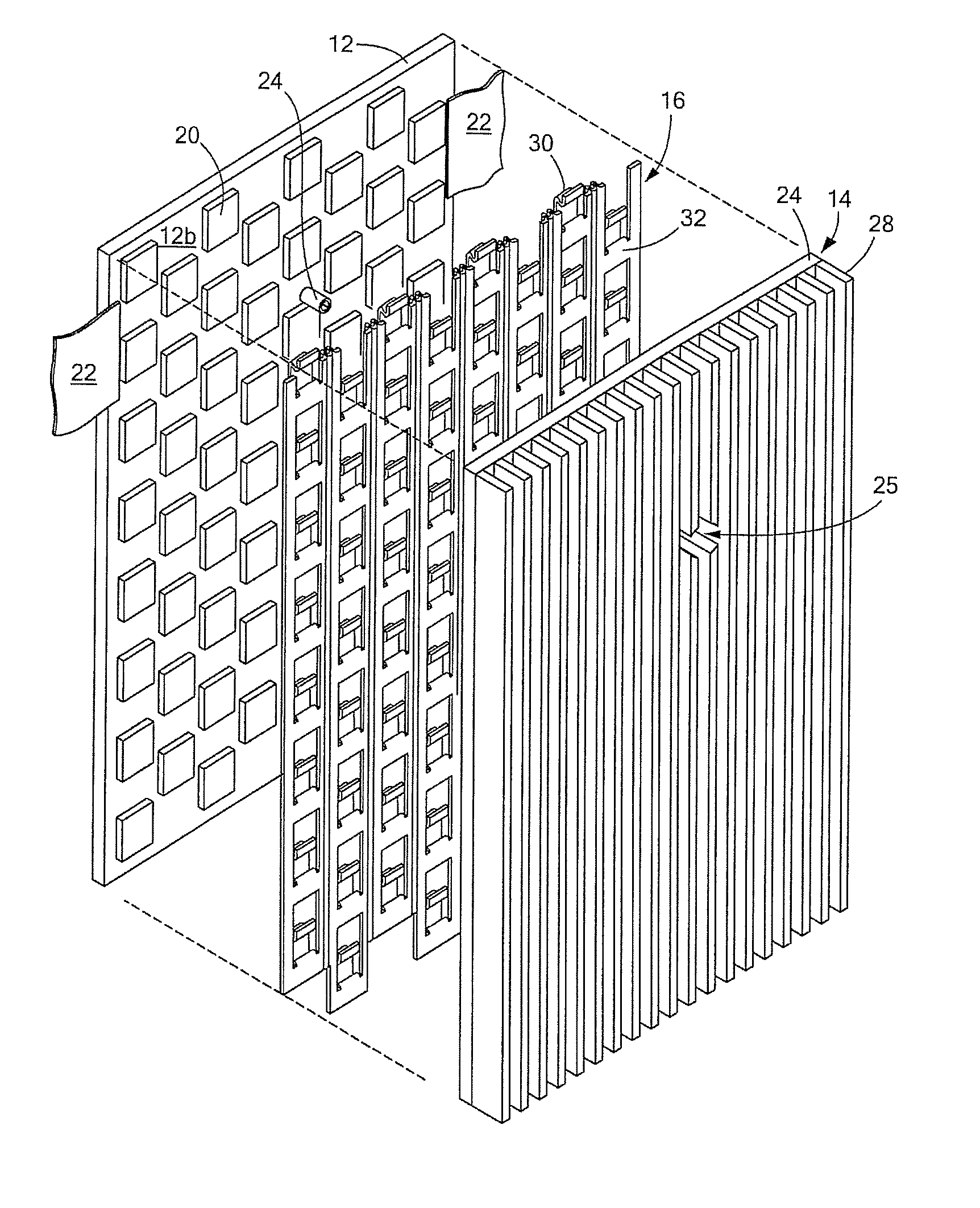
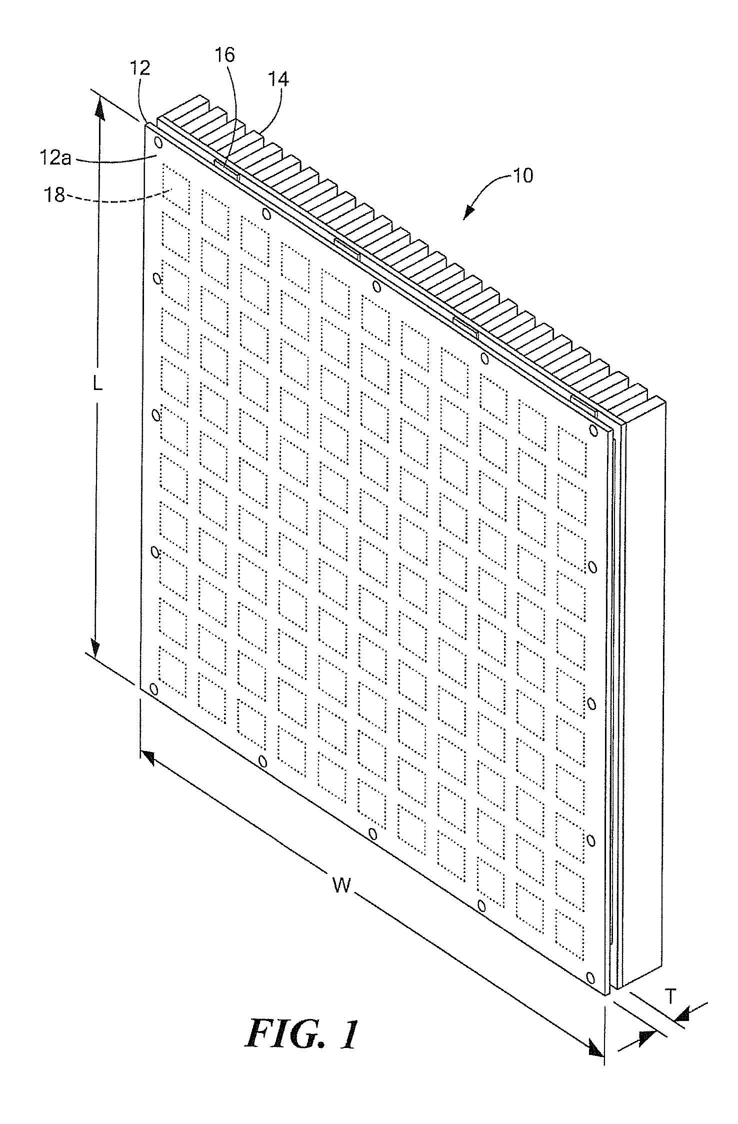
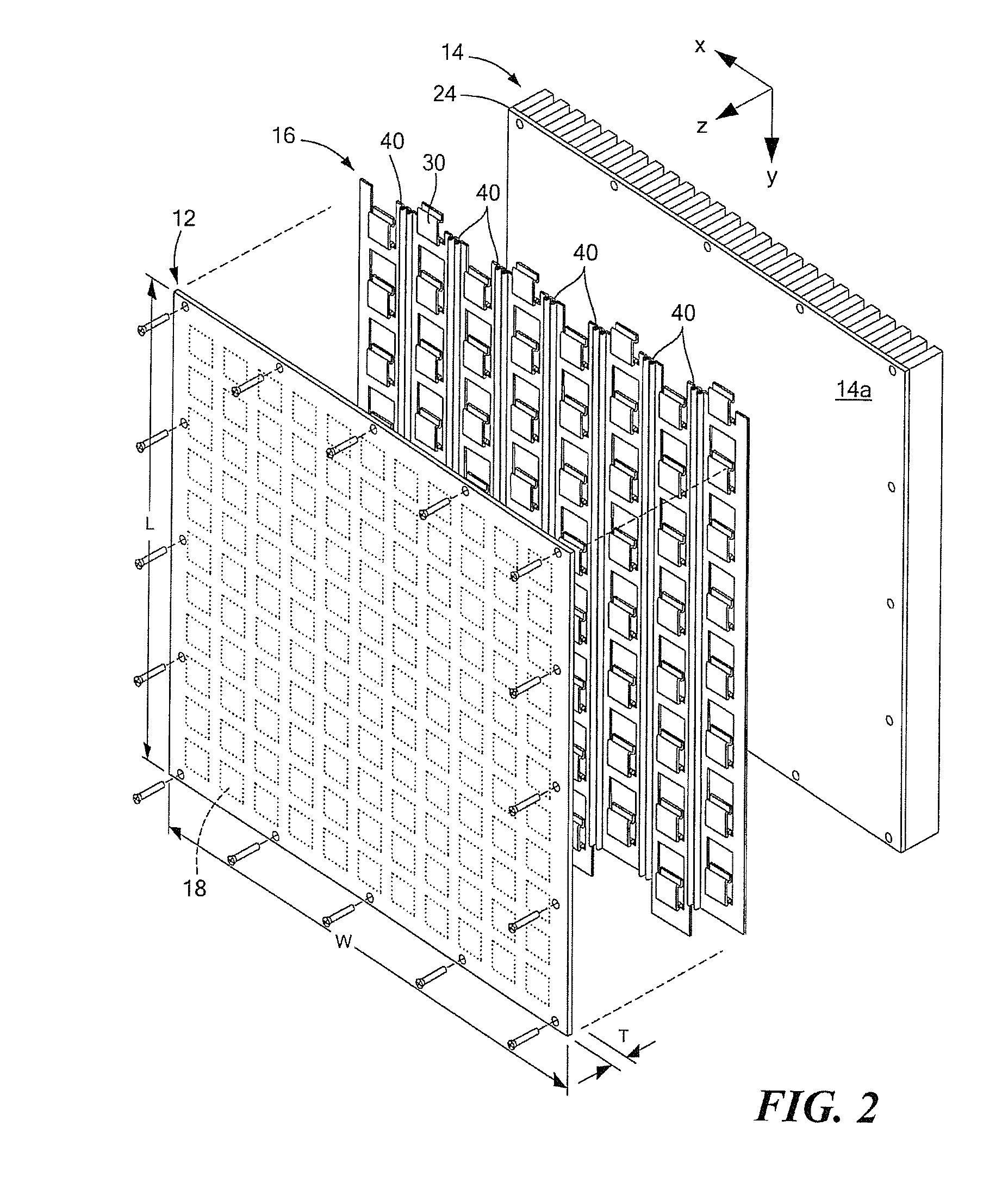
[0039]Described herein is a structure which acts as a mechanical and thermal interface between a heat generating device (e.g. a heat generating radio frequency circuit) and a heat sink. The interface compensates for mechanical tolerances in three dimensions. The interface is also sometimes referred to herein as a “thermal interface,” a “thermal cushion,” or a “heat sink interface.”

[0040]The thermal interface is described herein in the context of an “active panel array” antenna. It should be appreciated, however, that the thermal interface and concepts described herein, may also be used with other heat generating devices and is not limited to use with active panel array antennas. Rather, the thermal interface and concepts can be used with any radio frequency (RF) circuit which utilizes a heat sink. The thermal interface may also find application with other types ...


PUM


Abstract

A thermal interface includes a plurality of elevated regions and a plurality of mechanical tolerance circuits coupled to the plurality of elevated regions. The thermal interface is configured to be disposed between an array of heat generating elements and a heat sink with each of the plurality of elevated regions thermally coupled to a corresponding one or more of the array of heat generating elements. In one embodiment, the thermal interface provides a thermal path between a printed wiring board having a plurality of flip-chip circuit components disposed on an external surface thereof and a heat sink disposed over the flip-chip circuit components.

Description

CROSS-REFERENCE TO RELATED APPLICATIONS[0001]Not applicable.FIELD OF THE INVENTION[0002]The structures and techniques described herein relate to thermal management and more particularly to a thermal interface.BACKGROUND OF THE INVENTION[0003]As is known in the art, a phased array antenna includes a plurality of antenna elements spaced apart from each other by known distances. Each of the antenna elements are typically coupled through a plurality of phase shifter circuits, amplifier circuits and / or other circuits to either or both of a transmitter or receiver. In some cases, the phase shifter, amplifier circuits and other circuits (e.g. mixer circuits) are provided in a so-called transmit / receive (T / R) module and are considered to be part of the transmitter and / or receiver.[0004]The phase shifters, amplifier and other radio frequency (RF) circuits (e.g. T / R modules) are often powered by an external power supply (e.g. a DC power supply). Such circuits are referred to as “active circui...

Claims


Application Information

Patent Timeline
Patent Type & Authority Applications(United States)
IPC IPC(8): H05K7/20F28F7/00
CPCH05K7/20509
Inventor PAQUETTE, JEFFREYCHEYNE, SCOTT R.ELLSWORTH, JOSEPH R.MARTINEZ, MICHAEL P.TRAHAN, MICHAEL R.
Owner RAYTHEON CO
Why Eureka
Try Eureka