System, method and apparatus for tolerance ring control of slip interface sliding forces

a technology of tolerance rings and sliding forces, applied in the field of tolerance rings, can solve problems such as increasing frictional forces, and achieve the effect of reducing radial stiffness and resistan

Inactive Publication Date: 2011-03-31
SAINT GOBAIN PERFORMANCE PLASTICS RENCOL
View PDF97 Cites 102 Cited by
  • Summary
  • Abstract
  • Description
  • Claims
  • Application Information

AI Technical Summary

Benefits of technology

[0007]In other embodiments, an assembly comprises an outer component, an inner component located in the outer component and movable relative thereto, and a tolerance ring mounted between the inner and outer components. The tolerance ring provides a radial stiffness that is greater than about 20,000 N / mm and parameters selected from the following: a slip torque in a range of 1 to 25 Nm, and a diameter of less than about 40 mm; a slip torque in a range of 1 to 100 Nm, and a diameter of more than 40 mm; or a low resistance to axial sliding in a range of 10 to 600 N, and a diameter of more than 10 mm. Applications having smaller diameters may provide a lower radial stiffness.

Problems solved by technology

These requirements between the inner and outer components require strong and substantial contact, which increases frictional forces.

Method used


Image

  • System, method and apparatus for tolerance ring control of slip interface sliding forces
  • System, method and apparatus for tolerance ring control of slip interface sliding forces
  • System, method and apparatus for tolerance ring control of slip interface sliding forces

Examples


Embodiment Construction

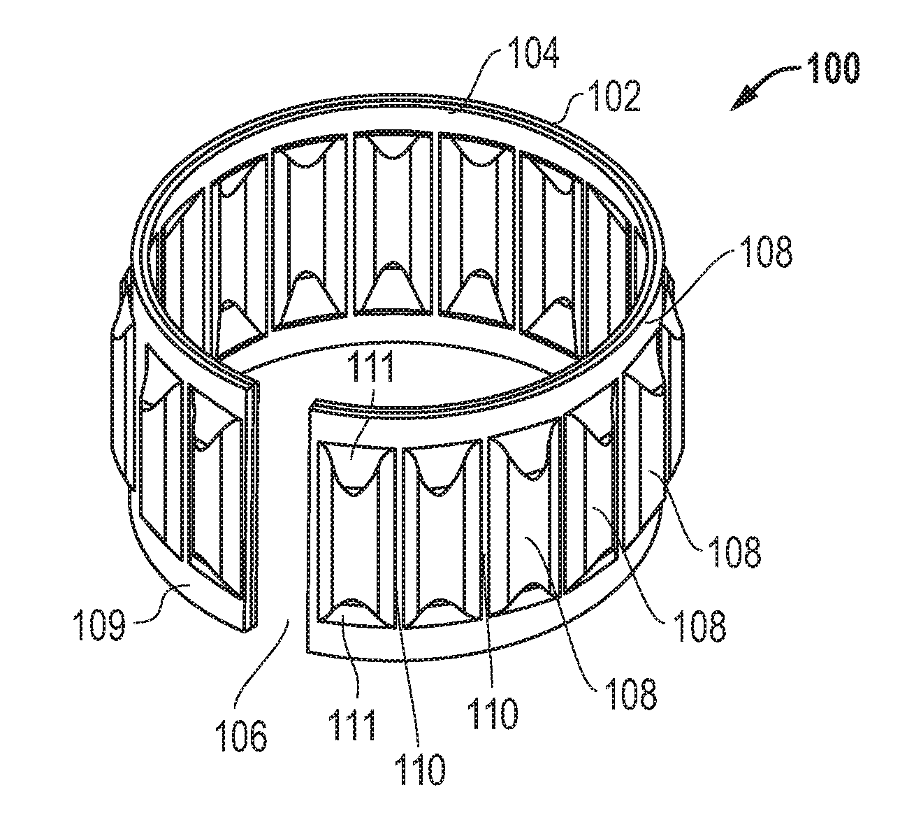
[0018]FIG. 1 depicts a tolerance ring 100 comprising one embodiment. The tolerance ring 100 comprises a band 102 of resilient material (e.g. spring steel) that is curved into a ring-like (substantially annular) shape. The ends of the band 102 do not meet (e.g., it may be formed as a split ring), thereby leaving an axially-extending gap 106 adjacent the circumference of the band. In other embodiments, the band may be curved so that the ends overlap with one another. In yet further embodiments, the band may be a continuous, unbroken ring. The inner surface of the tolerance ring 100 has a low friction layer 104 that conforms to the shape of the band.

[0019]The tolerance ring 100 has a plurality of spaced projections 108 that extend radially outward from the outer surface of the tolerance ring 100. There is a flat, circumferentially-extending rim 109 of material at each axial end of the projections 108. Each projection 108 also is separated from its neighboring projections by a flat sect...


PUM


Abstract

A tolerance ring comprising a metallic band for spring features and a complementary low friction material for frictional considerations is disclosed. The tolerance ring is designed to operate within a precisely controlled torque or axial force band to provide a defined amount of resistance and sliding force control between components that move relative to each other. Isolated portions of the tolerance ring form regions of contact with adjacent ones of the components. Other surfaces of the tolerance ring comprise portions with spring features that have geometry suitable for their spring rate, rather than conforming to mating surfaces of the adjacent components.

Description

[0001]This application claims priority to and the benefit of U.S. Provisional App. No. 61 / 245,883, filed Sep. 25, 2009, and is incorporated herein by reference in its entirety.FIELD OF THE DISCLOSURE[0002]The invention generally relates to tolerance rings that are located between moving parts and, in particular, to an improved system, method and apparatus employing a tolerance ring.BACKGROUND[0003]Tolerance rings constrain movement between relatively moving parts, such as rotating shafts in housing bores. One type of tolerance ring is an annular band located in the gap between the outer surface of the shaft and the inner surface of the bore. This tolerance ring limits radial motion of the shaft within the bore while still permitting rotation.[0004]In conventional tolerance ring configurations, a close fit between the inner and outer components is sought. In addition, either forces for providing maximal frictional engagement or minimal variation in sliding forces are sought. A close ...

Claims


Application Information

Patent Timeline
Patent Type & Authority Applications(United States)
IPC IPC(8): F16B2/22
CPCF16C27/02F16D3/06Y10T403/7058Y10T403/7061F16D1/0835F16D7/021Y10T156/1041F16C29/002F16C11/04F16D1/06F16D7/02
Inventor SLAYNE, ANDREWNATU, PARAG
Owner SAINT GOBAIN PERFORMANCE PLASTICS RENCOL
Why Eureka
Try Eureka