Dynamic Protective Envelope for Crane Suspended Loads

a protective envelope and crane technology, applied in the field of crane suspended loads, can solve the problems of inability to personally see the container, damage to the spreader, the crane operating mechanism and/or the target container, etc., and achieve the effect of avoiding collisions

Active Publication Date: 2011-03-31
TMEIC
View PDF12 Cites 47 Cited by
  • Summary
  • Abstract
  • Description
  • Claims
  • Application Information

AI Technical Summary

Benefits of technology

This invention relates to a computerized system for using a crane to transport loads having known dimensions from one location to another along a known path. The crane typically has a boom located above the known path, a trolley movably attached thereto and a spreader flexibly attached to the underside of the trolley. Movement of the trolley and the spreader are typically controlled by separate motors. A transceiver for sending and receiving pulses at a known speed is attached to the trolley, while a structured target is attached to the top surface of the spreader. The method relates to a process for avoiding collisions between the load and any objects situated in the known path. A first dynamic two-dimensional, rectangular digital representation in the X and Z axes of the spreader and any load attached thereto is constructed and stored in the computer. This first representation is the dynamic protective envelope for the spreader and its load, if any. Then, a second digital two-dimensional representation of a profile of the known path in the X and Z axes is constructed by the computer by determining the distance from the transceiver to the path

Problems solved by technology

However, due to the distances involved and the physical positioning of the spreader and container, the operators are frequently unable to personally see the container which they are handling or the target area for the spreader.
If the spreader speed is reduced too soon, the operating cycles

Method used


Image

  • Dynamic Protective Envelope for Crane Suspended Loads
  • Dynamic Protective Envelope for Crane Suspended Loads
  • Dynamic Protective Envelope for Crane Suspended Loads

Examples


Embodiment Construction

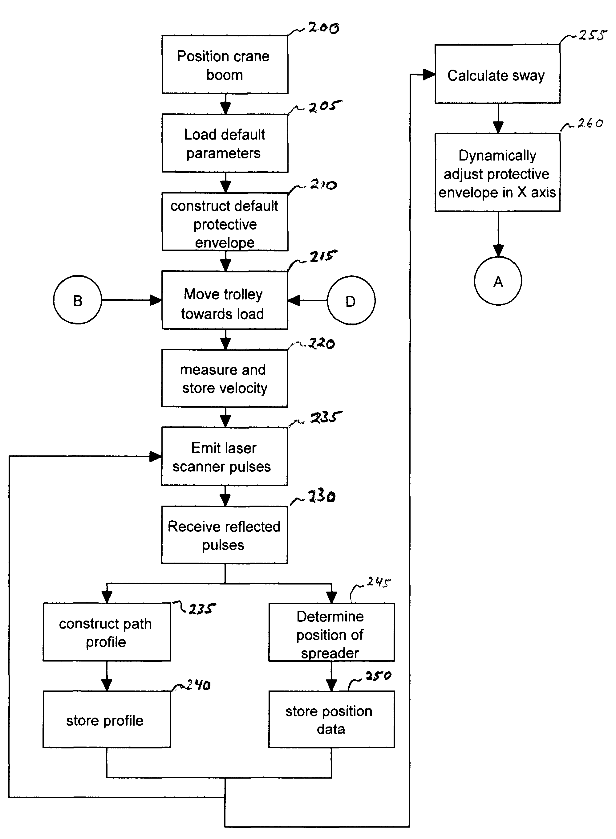
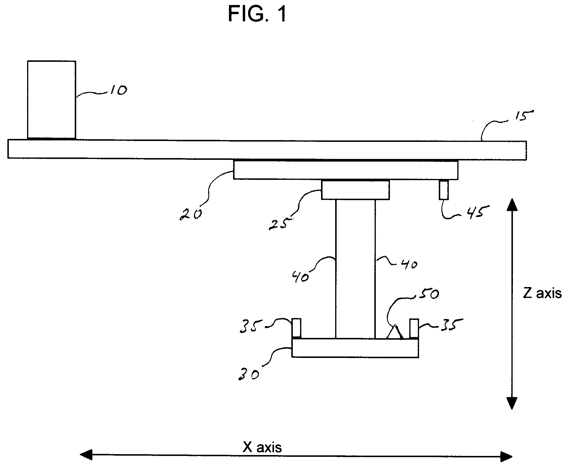
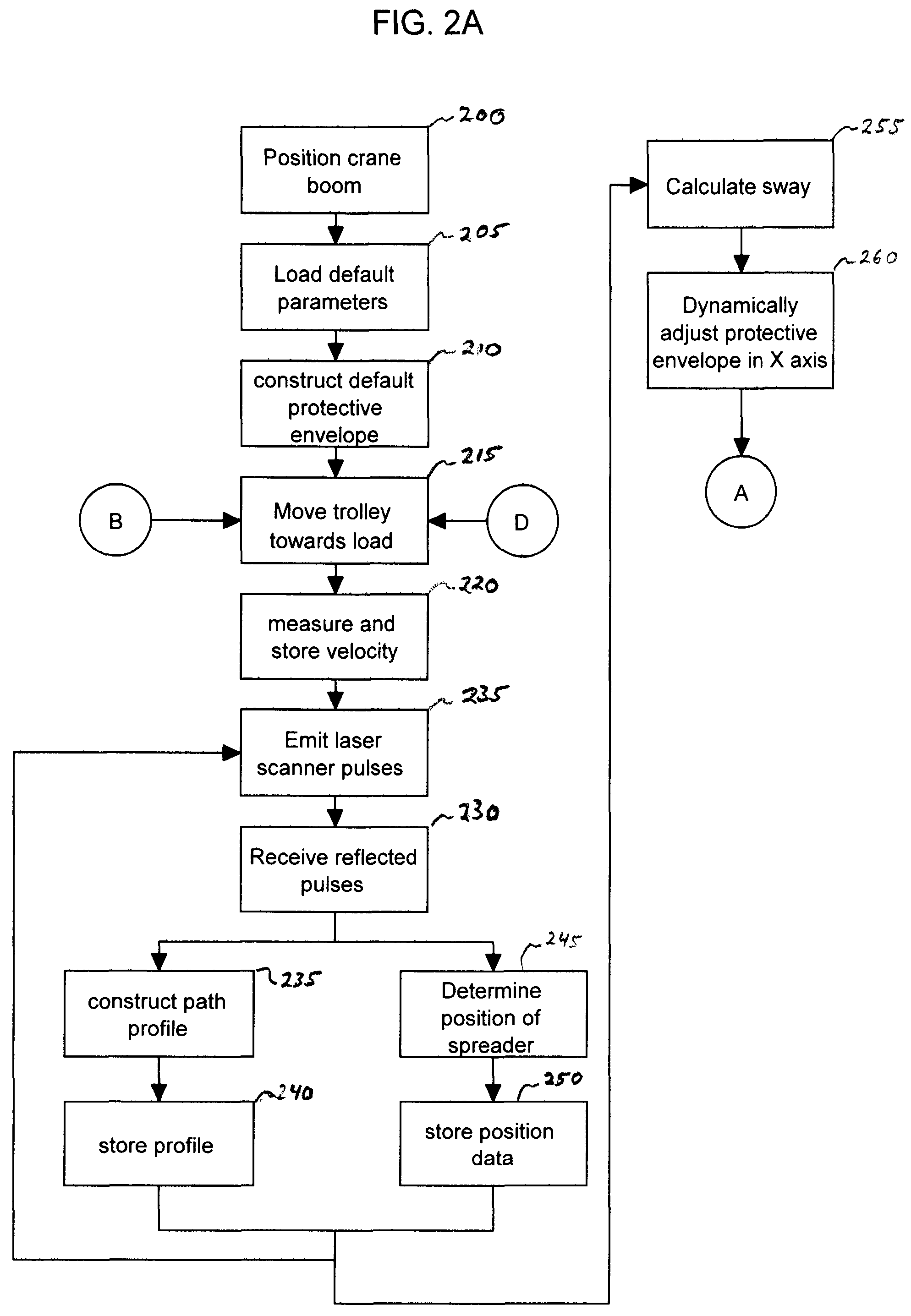
A gantry crane is typically used for loading and unloading containers located both on deck and in storage holds of ships as well as in on-shore holding yards. FIG. 1 presents a schematic view of the typical main components of such a gantry crane as used in this invention. These components are cabin 10 for housing crane controls, computer equipment including a processor, data storage device and display device and the crane driver or operator, boom 15, trolley 20 horizontally movable along boom 15, hoist 25 attached to trolley 20, spreader 30 having loading flippers 35 of a type known in the industry located at least at each corner thereof which spreader is affixed to hoist 25 typically with wire ropes 40, chains or other similarly flexible means, at least one laser scanner 45 functioning as a transceiver mounted on trolley 20 approximately 9 feet in front of spreader 30 and at least one prism-shaped laser target 50 mounted on the top of the head block of spreader 30. Trolley 20 moves...


PUM


Abstract

A system and method for using a gantry crane to efficiently and safely transport loads such as containers and ship hatch covers from one location to another along a known path while avoiding collisions between the loads and obstructing objects which may be situated in the known path. A transceiver emitting laser beams may be used to establish both the position of the spreader and its load and the profile of the known path. Continuous comparisons are made by computer between the location of a dynamic digital protective envelope constructed around the crane spreader and its load, if any, and a digital representation of the profile of the known path to be traveled by the spreader and its load, if any. In the event, the comparison indicates intersection of the protective envelope and the path profile, a speed limit is imposed on the motor controlling the movement in the X axis of the trolley or in the Z axis of the spreader, as required to prevent a collision.

Description

TECHNICAL FIELDThe subject invention relates generally to a system and method for use in comparing the positions of two objects and regulating the speed of the first of these objects which is mobile as it is brought into close proximity with the second immobile object. More particularly, this invention may be used in loading and unloading shipping containers with a mobile crane structure by sensing the position of a crane spreader mechanism relative to a container or other object as it approaches the container from an overhead position and imposing a speed limit on the hoist and / or trolley as the spreader approaches a container.BACKGROUND OF THE INVENTIONAutomatic container handling is typically accomplished by means of a crane having a generally rectangular shaped movable trolley located on a repositionable frame. A generally rectangular shaped spreader is used both to move containers onto a stack located on the ground or on a ship beneath the frame and to pick up target containers...

Claims


Application Information

Patent Timeline
IPC IPC(8): B66C1/16B66C13/06
CPCB66C13/46B66C19/002B66C15/045
Inventor STOCKER, DAVID G.BARTEL, MICHAEL G.
Owner TMEIC
Why Eureka
Try Eureka