
Method to improve fuel cell system performance using cell voltage prediction of fuel cell stack

a fuel cell and voltage prediction technology, applied in chemical methods analysis, electrochemical generators, instruments, etc., can solve the problems of difficult to define the relationship between the voltage and the current of the stack, the relationship between the current and the voltage of the stack is typically difficult to define, and the cost of manufacturing methods is relatively high

Inactive Publication Date: 2011-03-31
GM GLOBAL TECH OPERATIONS LLC
View PDF10 Cites 15 Cited by
  • Summary
  • Abstract
  • Description
  • Claims
  • Application Information

AI Technical Summary

Benefits of technology

[0012]In accordance with the teachings of the present invention, a system and method are disclosed for determining the maximum allowed stack current limit rate for a fuel cell stack that considers cell voltage. The method includes estimating a fuel cell stack voltage based on a fuel cell resistance value, stack variables and a current request signal. The fuel cell resistance value can be modeled based on stack tem

Problems solved by technology

MEAs are relatively expensive to manufacture and require certain conditions for effective operation.
The relationship between the voltage and the current of the stack is typically difficult to define because it is non-linear, and changes depending on many variables, including stack temperature, stack partial pressures and cathode and anode stoichiometries.
Additionally, the relationship between the stack current and voltage changes as the stack degrades over time.
However, such a current rate limit process does not lead to optimal performance of the fuel cell stack.
Particularly, the current rate limit is not the quickest for all temperature and relative humidity values for various stack operating conditions, and thus, more than the stack temperature and relative humidity determine stack performance.
For example, because the current rate limit is not based on cell voltage, the current rate limit may cause the voltage of a fuel cell within the stack to drop too quickly, which could damage the stack.

Method used


Image

  • Method to improve fuel cell system performance using cell voltage prediction of fuel cell stack
  • Method to improve fuel cell system performance using cell voltage prediction of fuel cell stack
  • Method to improve fuel cell system performance using cell voltage prediction of fuel cell stack

Examples


Embodiment Construction

[0017]The following discussion of the embodiments of the invention directed to a system and method for determining the maximum allowed stack current limit rate for a fuel cell stack that uses an estimated cell voltage is merely exemplary in nature, and is in no way intended to limit the invention or its applications or uses.

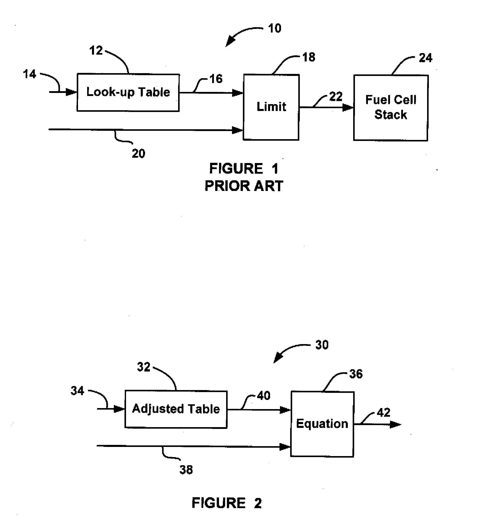
[0018]FIG. 1 is a schematic block diagram of a current set-point system 10 of the type known in the art and discussed above. The system 10 includes a look-up table 12 that receives temperature and relative humidity input signals on line 14. Based on the temperature and relative humidity input signals, the look-up table 12 provides a current rate limit value R on line 16 that is sent to a limit processor 18. The limit processor 18 also receives a current request value Ireq on line 20 that identifies a current set-point value Isp to be provided to a fuel cell stack 24, typically from a vehicle driver request, on line 22. The limit processor 18 provides the current ...


PUM


Abstract

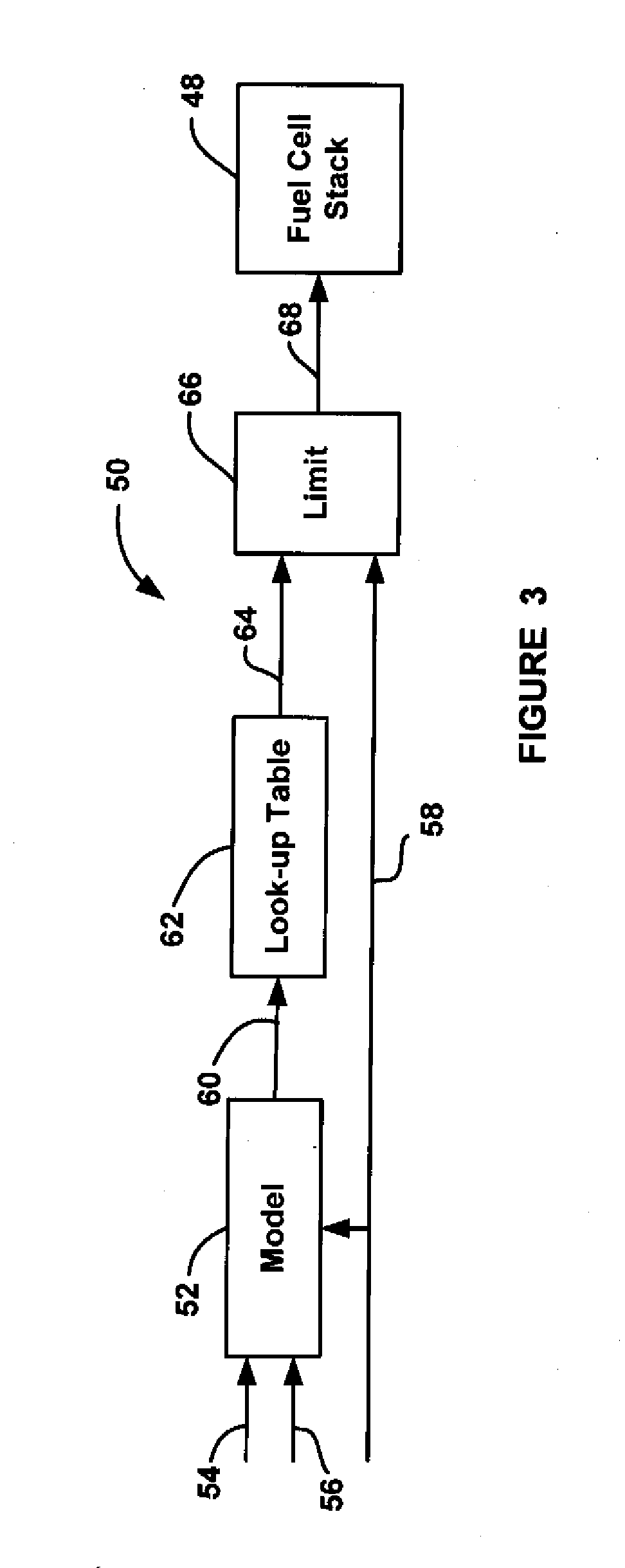
A system and method for determining the maximum allowed stack current limit rate for a fuel cell stack that considers cell voltage. The method includes estimating a fuel cell stack voltage based on a fuel cell resistance value, stack variables and a current request signal. The fuel cell resistance value can be modeled based on stack temperature and stack relative humidity. The stack variables can include exchange current density and mass transfer coefficient. The method then uses the estimated fuel cell voltage and a look-up table based on estimated voltage to determine a current rate limit value for changing the current of the stack. The method then adds the current rate limit value and the current request signal to obtain the current set-point.

Description

BACKGROUND OF THE INVENTION[0001]1. Field of the Invention[0002]This invention relates generally to a system and method for predicting the voltage of a fuel cell stack and determining the maximum allowed stack current limit rate for a fuel cell stack and, more particularly, to a system and method for determining the maximum allowed stack current limit rate for a fuel cell stack that includes using an estimated cell voltage.[0003]2. Discussion of the Related Art[0004]Hydrogen is a very attractive fuel because it is clean and can be used to efficiently produce electricity in a fuel cell. A hydrogen fuel cell is an electro-chemical device that includes an anode and a cathode with an electrolyte therebetween. The anode receives hydrogen gas and the cathode receives oxygen or air. The hydrogen gas is dissociated in the anode to generate free hydrogen protons and electrons. The hydrogen protons pass through the electrolyte to the cathode. The hydrogen protons react with the oxygen and the...

Claims


Application Information

Patent Timeline
IPC IPC(8): H01M8/00H01M8/04G06F19/00
CPCH01M8/0432H01M8/04492H01M8/04559Y02E60/50H01M8/04992H01M2008/1095H01M8/04589
Inventor ZHANG, YANYANGANAPATHY, SRIRAMDEVRIES, LORENCLINGERMAN, BRUCE J.
Owner GM GLOBAL TECH OPERATIONS LLC
Learn More