
Microwave Surface Ablation Using Conical Probe

Active Publication Date: 2011-03-31
TYCO HEALTHCARE GRP LP
View PDF62 Cites 86 Cited by
  • Summary
  • Abstract
  • Description
  • Claims
  • Application Information

AI Technical Summary

Benefits of technology

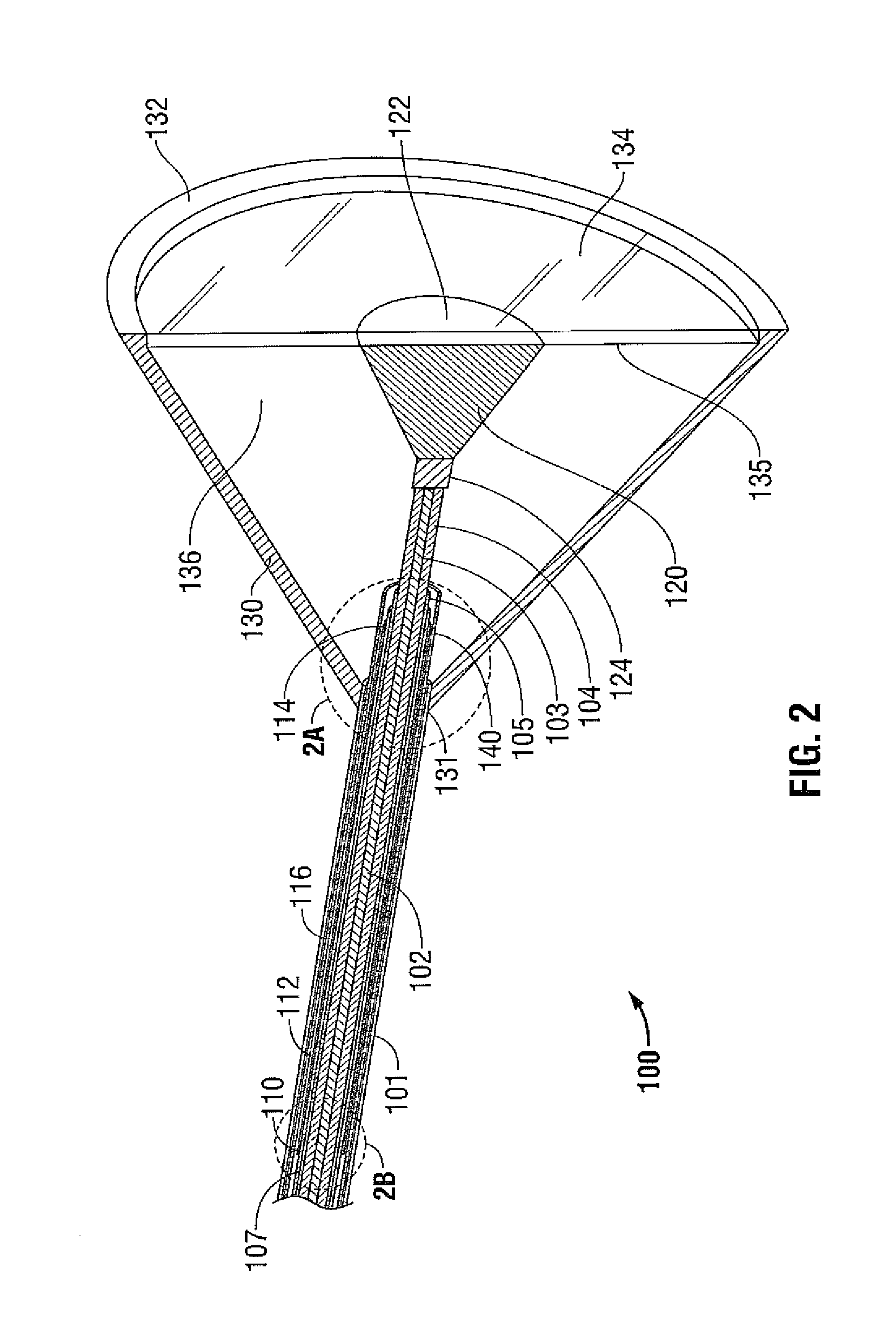
[0010]Radiofrequency energy is supplied to the antenna by a coaxial feedline having an inner conductor, an outer conductor disposed coaxially thereabout, and a dielectric disposed therebetween. The coaxial feedline passes longitudinally from a proximal end of the antenna, through the catheter, to a distal end of the antenna. A radiating section disposed within the conical hood is electrically coupled to the inner conductor. The radiating section may have a conical shape having a narrow proximal end coupled to the inner conductor, and a wide distal end extending toward the radiofrequency-transparent membrane or plate. The radiating section may additionally or alternatively include a flared section, a spiral section, and / or be loaded with disks, which may improve radiating performance and mechanical strength. Additionally or alternatively, the inner conductor may include a sharp tip that protrudes beyond the distal end of the conical opening, or may terminate within the cone. During use, the sharp tip may assist in positioning the antenna on tissue, and / or may improve radiation performance.

Problems solved by technology

However, at slightly elevated temperatures above the approximate range of 43° C. to 45° C., thermal damage to most types of normal cells is routinely observed.
Such surface lesions have been treated with invasive ablation needles or sticks, which may cause damage to adjacent anatomical structures, increase the likelihood of hemorrhaging, and lengthen operative and recovery times.

Method used


Image

  • Microwave Surface Ablation Using Conical Probe
  • Microwave Surface Ablation Using Conical Probe
  • Microwave Surface Ablation Using Conical Probe

Examples


Embodiment Construction

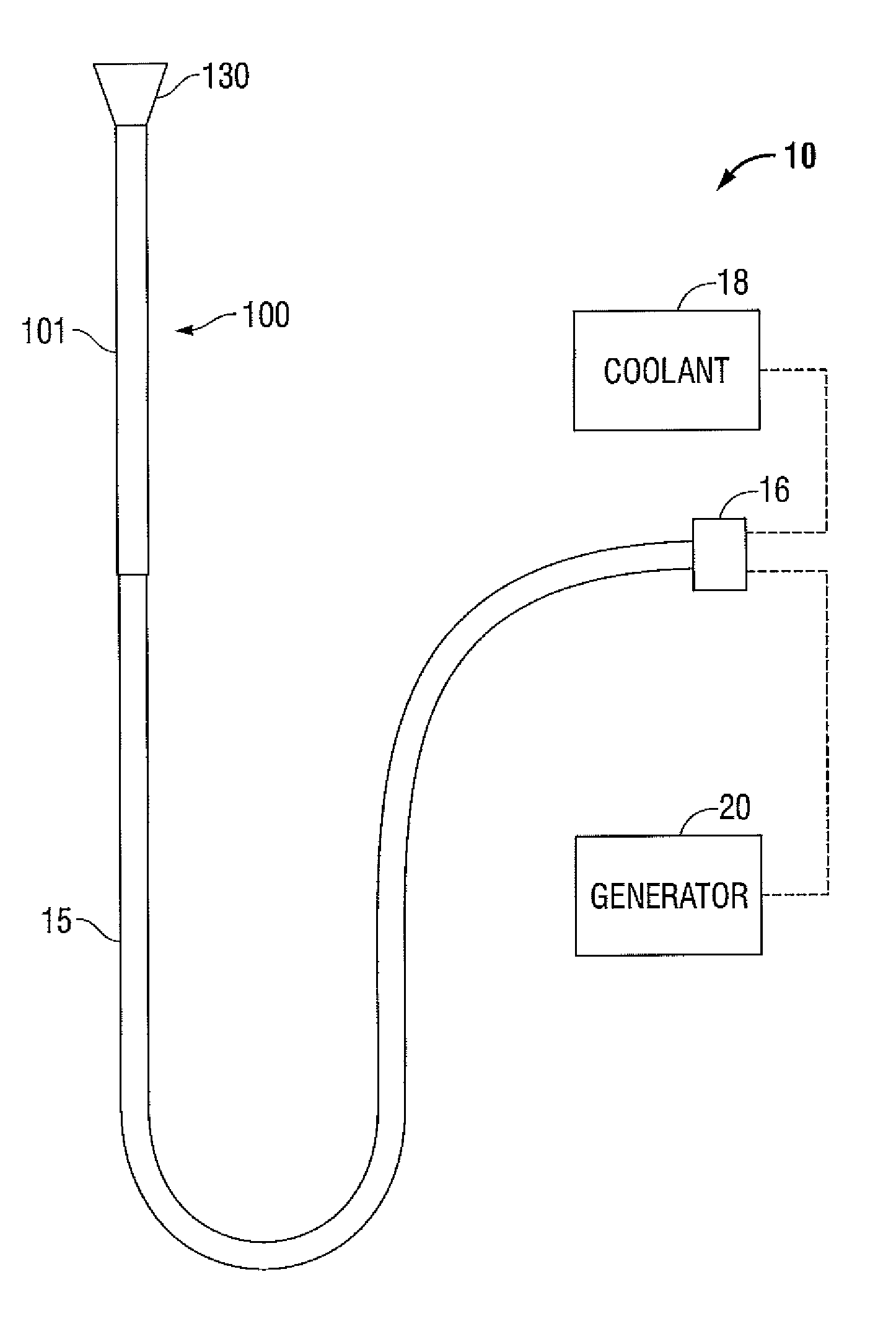
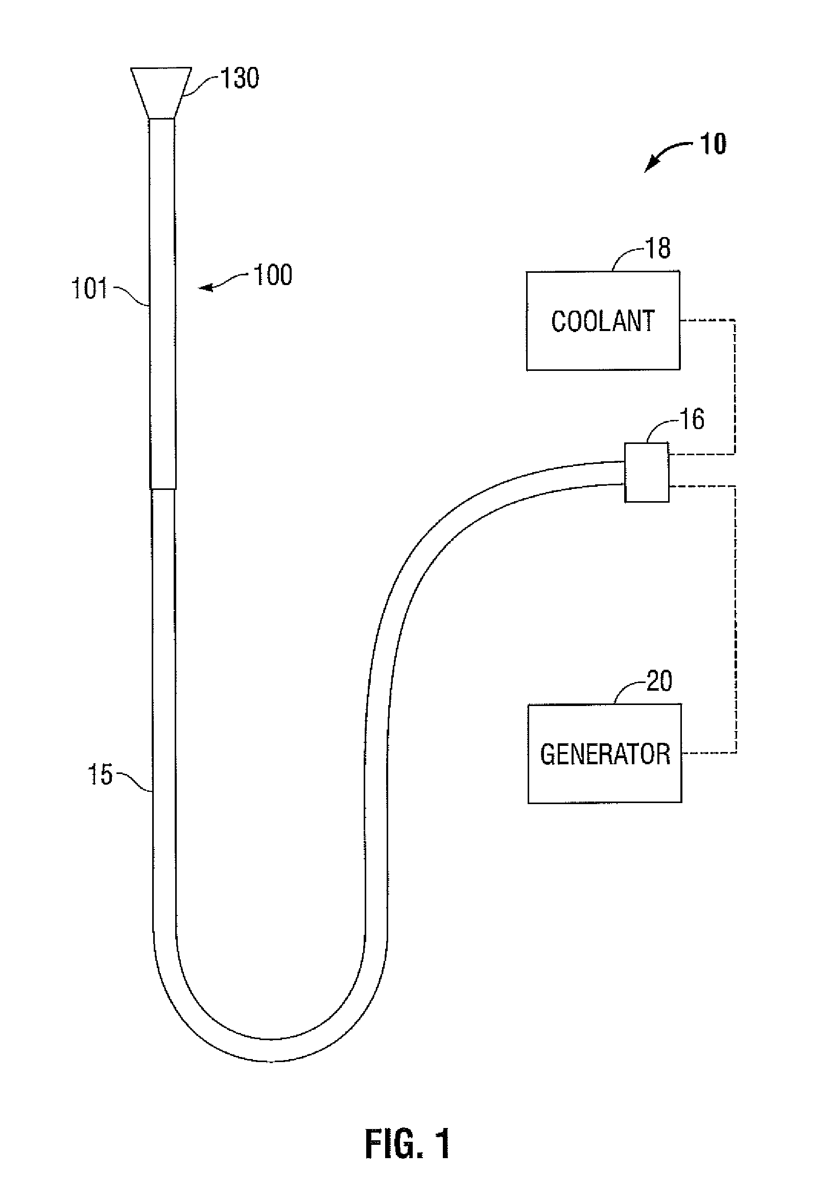
[0029]Particular embodiments of the present disclosure will be described hereinbelow with reference to the accompanying drawings; however, it is to be understood that the disclosed embodiments are merely exemplary of the disclosure, which may be embodied in various forms. Well-known or repetitive functions, constructions are not described in detail to avoid obscuring the present disclosure in unnecessary or redundant detail. Therefore, specific structural and functional details disclosed herein are not to be interpreted as limiting, but merely as a basis for the claims and as a representative basis for teaching one skilled in the art to variously employ the present disclosure in virtually any appropriately detailed structure.

[0030]In the drawings and in the descriptions that follow, the term “proximal,” as is traditional, shall refer to the end of the instrument that is closer to the user, while the term “distal” shall refer to the end that is farther from the user.

[0031]FIG. 1 show...


PUM

PropertyMeasurementUnit
Temperatureaaaaaaaaaa
Dielectric polarization enthalpyaaaaaaaaaa
Electrical conductivityaaaaaaaaaa

Abstract

An electromagnetic surgical ablation probe having a conical hood reflector and method of manufacture thereof is disclosed. The disclosed probe includes a shaft assembly that has a coaxial feedline core having an inner conductor and an outer conductor separated by an insulating layer. A tubular catheter is disposed coaxially around the feedline and is configured to deliver coolant, such as saline or deionized water, to a coolant chamber at a distal end formed within the conical reflector. A radiating section disposed within the conical reflector may have a conical, cylindrical, or other suitable shape. A membrane disposed across a distal opening of the conical reflector seals coolant within the coolant chamber, and may conform to tissue contours during use. A resilient aperture may be included at the periphery of the conical hood. The shaft assembly may include an angled section, an adjustable section, and, additionally or alternatively, a malleable section.

Description

BACKGROUND[0001]1. Technical Field[0002]The present disclosure relates to systems and methods for providing energy to biological tissue and, more particularly, to a microwave ablation surgical antenna having a conical aperture, and methods of use and manufacture therefor.[0003]2. Background of Related Art[0004]Energy-based tissue treatment is well known in the art. Various types of energy (e.g., electrical, ultrasonic, microwave, cryogenic, thermal, laser, etc.) are applied to tissue to achieve a desired result. Electrosurgery involves application of high radio frequency electrical current to a surgical site to cut, ablate, coagulate or seal tissue. In monopolar electrosurgery, a source or active electrode delivers radio frequency energy from the electrosurgical generator to the tissue and a return electrode carries the current back to the generator. In monopolar electrosurgery, the source electrode is typically part of the surgical instrument held by the surgeon and applied to the ...

Claims


Application Information

Patent Timeline
IPC IPC(8): A61B18/18H01P11/00
CPCA61B18/18A61B18/1815Y10T29/49016A61B2018/1853A61B2018/1861A61B2018/00023
Inventor BRANNAN, JOSEPH D.
Owner TYCO HEALTHCARE GRP LP
Learn More