Multi-stage Pressure Equalization Valve Assembly for Subterranean Valves

a technology of equalizing valve and subterranean valve, which is applied in the direction of sealing/packing, pressure relieving devices on the sealing face, and borehole/well accessories. it can solve the pressure differential between the passage inside the ball and the downhole pressure, and the operator's money is a lot of money

Active Publication Date: 2011-04-07
BAKER HUGHES INC
View PDF75 Cites 29 Cited by
  • Summary
  • Abstract
  • Description
  • Claims
  • Application Information

AI Technical Summary

Benefits of technology

[0006]A downhole valve that operates on turning of a member having a passage through it with a control system also features a passage from above an uphole seat for the member which communicates to the isolated passage within the member when the valve is closed. The passage features a check valve assembly that preferably has redundant sealing features and filters to prevent debris entry. Pressure applied from above the closed member gets through the check valve assembly to equalize the higher pressure below the ball with the pressure raised in the ball from pressure application at the surface. Removal of the applied pressure reseats the check valve or valves to allow the hydraulic system to rotate the member while the member is no longer subject to a high differential pressure.

Problems solved by technology

What can happen in this type of a ball valve that has upper and lower seats against the ball in the closed position is that pressure from downhole can rise, which leads to a pressure differential between the passage inside the ball and the downhole pressure.
This pressure differential can distort the ball and make it hard or impossible for the piston actuation system to operate the ball back into the open position.
The problem with this technique was that it required a run into the well with coiled tubing, latching and shifting the upper sleeve and associated seat enough to give access into the ball for equalizing pressure.
One of the downsides of this technique was that the pressure admitted to try to equalize the pressure in the ball could be high enough to unseat the lower seat from the ball so that the higher pressure below the ball would get to above the ball.
This technique also took time which cost the operator money and required specialized equipment at the well location, which could be remote or offshore and add yet additional costs to the effort to operate the ball when subjected to high differential pressures that could distort the ball enough to make it hard for the hydraulic system to rotate it.

Method used


Image

  • Multi-stage Pressure Equalization Valve Assembly for Subterranean Valves
  • Multi-stage Pressure Equalization Valve Assembly for Subterranean Valves
  • Multi-stage Pressure Equalization Valve Assembly for Subterranean Valves

Examples


Embodiment Construction

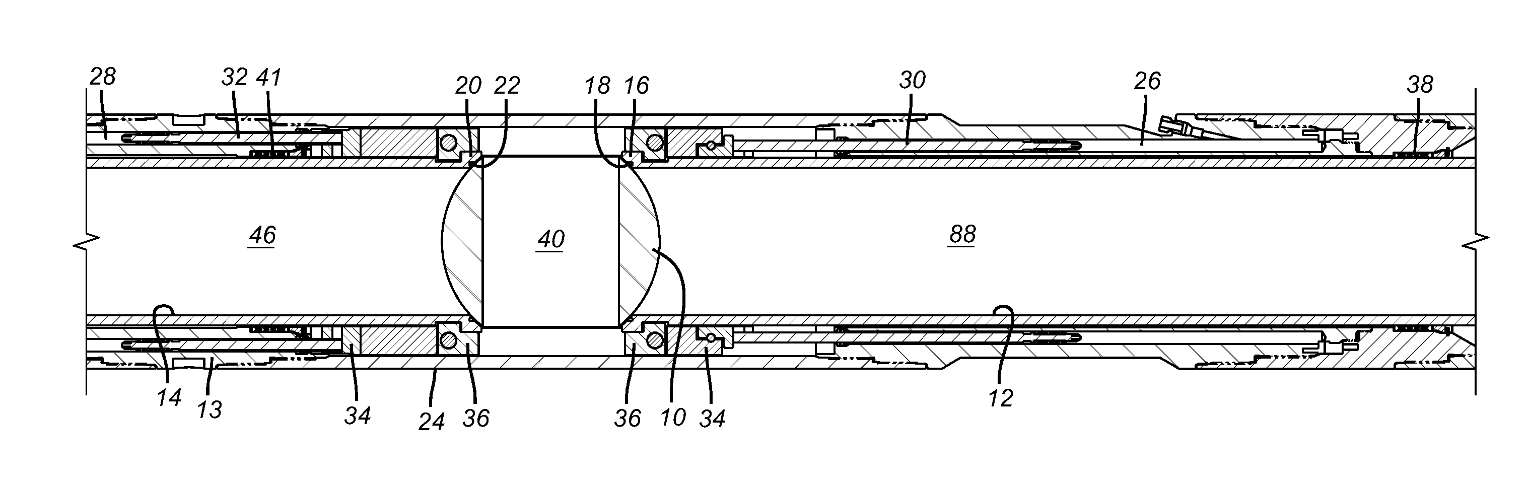
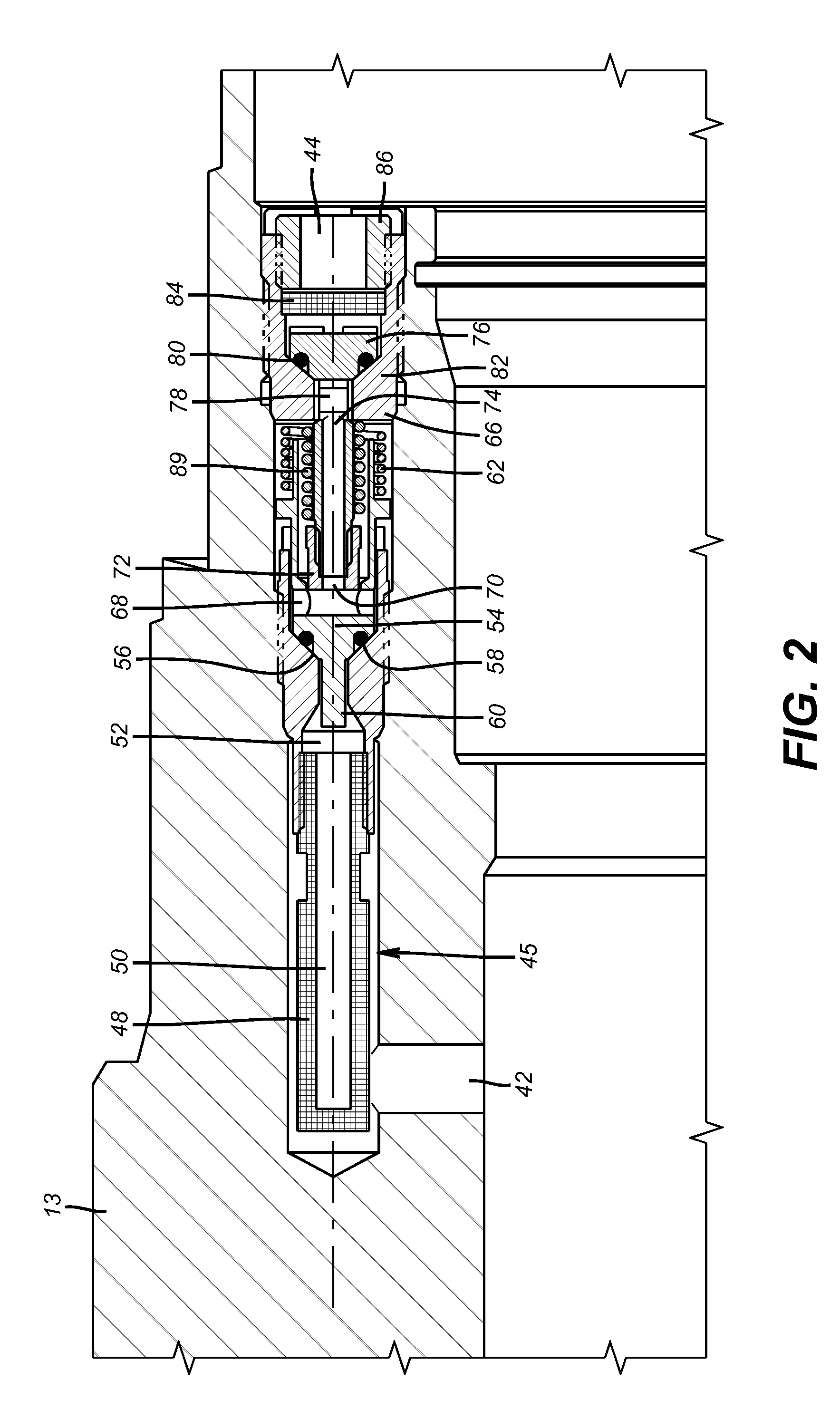
[0009]The basic components of the valve of FIG. 1 are reviewed in more detail in US Publication 2008 / 0110632 whose description is fully incorporated by reference herein as though full set forth. The portions of such valve relevant to the understanding of the present invention will be reviewed below in sufficient detail and for completeness so as to fully understand the operation of the claimed invention.

[0010]FIG. 1 shows a ball valve in the closed position. The ball 10 has a lower seat sleeve 12 below it and an upper seat sleeve 14 above it. Seat 16 with seal 18 is pushed by a spring assembly (not shown) against the ball 10. Seat 20 with seal 22 is supported against axial movement by the housing 24 such that the bias on the lower sleeve 12 pushes the seat 16 against the ball 10 and in turn pushes the ball 10 against the seat 20. Control lines (not shown) are in fluid communication with inlet passages 26 and 28 that respectively lead to operating pistons 30 and 32. Pistons 30 and 32...


PUM


Abstract

A downhole valve that operates on turning of a member having a passage through it with a control system also features a passage from above an uphole seat for the member which communicates to the isolated passage within the member when the valve is closed. The passage features a check valve assembly that preferably has redundant sealing features and filters to prevent debris entry. Pressure applied from above the closed member gets through the check valve assembly to equalize the higher pressure below the ball with the pressure raised in the ball from pressure application at the surface. Removal of the applied pressure reseats the check valve or valves to allow the hydraulic system to rotate the member while the member is no longer subject to a high differential pressure.

Description

FIELD OF THE INVENTION[0001]The field of this invention is an equalizing pressure feature for subterranean or downhole valves and more particularly a way to equalize trapped lower pressure in a ball or plug of a valve without having to run a tool in the valve.BACKGROUND OF THE INVENTION[0002]Downhole valves are used to isolate portions of the wellbore for a variety of reasons such as for safety systems or to allow building a long bottom hole assembly in the wellbore, to name a few examples. Such valves have featured a rotating ball with a bore through it that can be aligned or misaligned with the path through the tubing string where the valve is mounted. The ball is surrounded by a sliding cage that is operated by a hydraulic control system from the surface. One such design that features opposed pistons actuated by discrete control lines is illustrated in US Publication 2009 / 0184278. This design was concerned about a pressure imbalance on an operating piston and provided a passage t...

Claims


Application Information

Patent Timeline
Patent Type & Authority Applications(United States)
IPC IPC(8): E21B34/00
CPCE21B2034/002E21B34/101E21B2200/04Y10T137/7729Y10T137/86968
Inventor PLUNKETT, KEVIN R.MEGILL, MARK S.
Owner BAKER HUGHES INC
Why Eureka
Try Eureka