
Cavity structure comprising an adhesion interface composed of getter material

Active Publication Date: 2011-04-07
COMMISSARIAT A LENERGIE ATOMIQUE ET AUX ENERGIES ALTERNATIVES
View PDF10 Cites 62 Cited by
  • Summary
  • Abstract
  • Description
  • Claims
  • Application Information

AI Technical Summary

Benefits of technology

[0050]Depositing of the first and of the second portion of getter material may be done preferably on minimal thickness (for example equal to approximately 100 nm, or less than appr

Problems solved by technology

The encapsulation structure 10 has two major drawbacks:control of the airtightness of the sealing bead 20 after its fusion, which is difficult to obtain,the dimensions of the sealing bead 20 which are difficult to control as this bead risks spreading out during the fusion step, possibly causing dysfunctioning of the encapsulated device (affected mobile mass, short-circuit, etc.).
These treatments, made dry and / or humid, are only slightly compatible with the presence of a getter whereof they risk significantly reducing the pumping capacity and therefore limiting minimal pressure accessible by this type of structure.

Method used


Image

  • Cavity structure comprising an adhesion interface composed of getter material
  • Cavity structure comprising an adhesion interface composed of getter material
  • Cavity structure comprising an adhesion interface composed of getter material

Examples


first embodiment

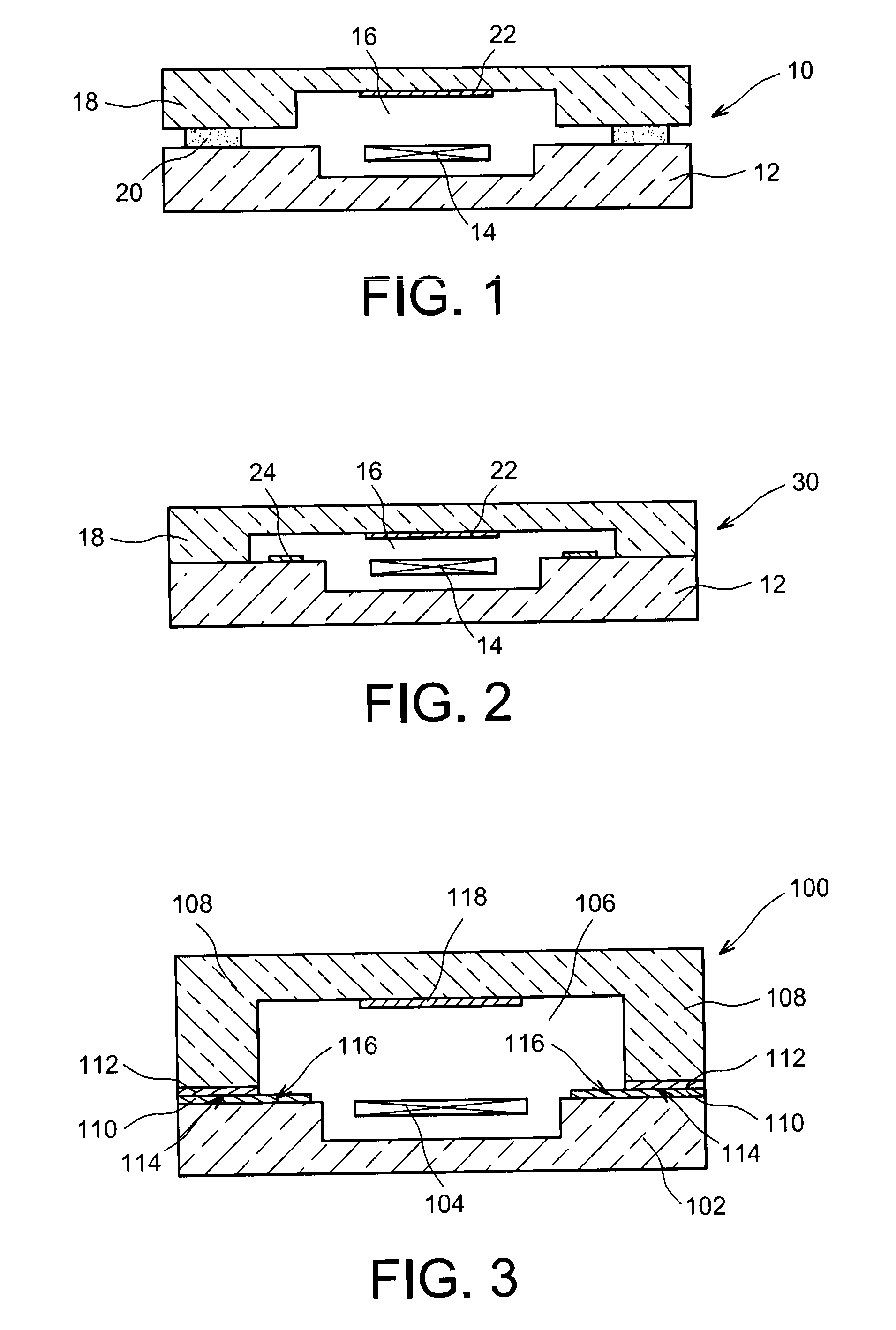
[0066]Reference is first made to FIG. 3 which illustrates a structure 100, here acting as encapsulation structure of a device 104, according to a

[0067]The structure 100 comprises a first substrate 102, for example composed of a semi-conductor such as silicon, on which the microelectronic and / or nanoelectronic device 104 is placed, for example of MEMS, NEMS, MOEMS, NOEMS type, or an infrared detector, for example of microbolometer type. The device 104 is encapsulated in a cavity 106 formed between the substrate 102 and a second substrate 108, also composed of a semi-conductor such as silicon, here forming a cover. The connection between the second substrate 108 and the first substrate 102 is made by means of a part 114 of a first portion of getter material 110 deposited on the first substrate 102, all over the device 104, and a second portion of getter material 112 deposited against the second substrate 108.

[0068]The first and second portions of getter material 110 and 112 have for e...

second embodiment

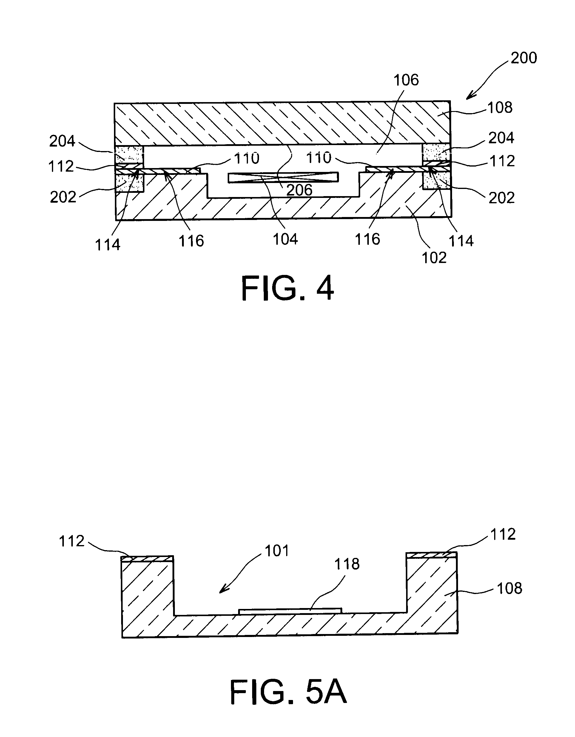
[0074]FIG. 4 illustrates a structure 200, here forming an encapsulation structure of the device 104, according to a Relative to the encapsulation structure 100 illustrated in FIG. 3, the encapsulation structure 200 comprises electrical contacts 202 formed in the first substrate 102 as well as electrical contacts 204 placed on a face 206 of the second substrate 108 forming a wall of the cavity 106.

[0075]The electrical contacts 202 and 204 are connected together electrically by means portions 110 and 112 of getter materials which are composed of metal. So, the portions 110 and 112 serve both to produce hermetic sealing between the second substrate 108 and the first substrate 102 but also to electrically connect together the electrical contacts 110 and 112. Also, the second part 116 of the first portion 110 of getter material, as in the encapsulation structure 100, also serves to absorb and / or adsorb the gases present in the cavity 106. Finally, relative to the encapsulation structure...


PUM


Abstract

A structure comprising a cavity delimited by a first substrate and a second substrate attached to the first substrate by an adhesion interface, in which a first part of a first portion of a getter material forms part of the adhesion interface, and a second part of the first portion of getter material is placed in the cavity, the first portion of getter material being placed against the first substrate or the second substrate, the adhesion interface further comprising part of a second portion of a getter material thermocompressed to the first part of the first portion of getter material, said second portion of getter material being placed against the second substrate when the first portion of getter material is placed against the first substrate or placed against the first substrate when the first portion of getter material is placed against the second substrate.

Description

TECHNICAL FIELD[0001]The invention relates to a structure comprising a cavity, for example hermetically sealed, in which a getter material is placed for controlling the atmosphere prevailing in the cavity, the getter material also serving to complete an adhesion interface between the elements forming the cavity. The structure may especially be an encapsulation structure of a microelectronic and / or nanoelectronic device. The invention also relates to a production method for such a structure.PRIOR ART[0002]For proper operation, some microelectronic and / or nanoelectronic devices such as those of MEMS type (electromechanical microsystem), NEMS (electromechanical nanosystem), MOEMS (opto-electromechanical microsystem), NOEMS (opto-electromechanical nanosystem) or even infrared detectors, need to be enclosed in a cavity whereof the atmosphere (nature of the gas, pressure) is controlled. These devices are generally made collectively on the same substrate (wafer) for example composed of sil...

Claims


Application Information

Patent Timeline
IPC IPC(8): H01L23/02H01L21/56
CPCB81B7/0038B81C2203/019H01L23/10H01L23/26H01L2924/0002H01L2924/00G01J5/045
Inventor BAILLIN, XAVIER
Owner COMMISSARIAT A LENERGIE ATOMIQUE ET AUX ENERGIES ALTERNATIVES
Features
  • Generate Ideas
  • Intellectual Property
  • Life Sciences
  • Materials
  • Tech Scout
  • Unparalleled Data Quality
  • Higher Quality Content
  • 60% Fewer Hallucinations
Learn More