
Synthetic quartz glass substrate and making method

a technology of synthetic quartz glass and substrate, applied in the field of synthetic quartz glass substrate, can solve the problems of increasing processing cost and time, and increasing processing cost and time, and achieves the effects of low defect density, minimal roughness, and high flatness

Active Publication Date: 2017-03-21
SHIN ETSU CHEM IND CO LTD
View PDF21 Cites 0 Cited by
  • Summary
  • Abstract
  • Description
  • Claims
  • Application Information

AI Technical Summary

Benefits of technology

The synthetic quartz glass substrate in this patent is perfect for use in photolithography to make finer images. It has a high flatness, low defect density, and minimal roughness on its surface. When this substrate is mounted on a stepper using suction chucking, it meets the specifications required for the process.

Problems solved by technology

However, the above methods for flattening substrates are inconvenient in the apparatus size and process flow, and the eventual increases in processing cost and time are outstanding problems.
For example, the gas cluster ion beam etching requires a time-consuming step of creating a vacuum environment prior to the start of processing, and the non-contact polishing such as float polishing is disadvantageous in that a longer polishing / processing time is needed due to a low polishing rate.
A greater capital of investment needed for the large size of apparatus and operation expenses including expensive gases necessary for the processing are reflected by the cost of substrate processing so that substrates may become more expensive.
Increases in the price of glass substrates are unfavorable to both the supply and demand sides.
However, with this area setting, flatness control is difficult because a shape change of the peripheral portion has a less influence on flatness within the effective range.
Accordingly, the proposal is short of capability for high-flatness substrates such as substrates for the EUVL that imposes a severe requirement on the flatness of substrate surface.

Method used


Image

  • Synthetic quartz glass substrate and making method
  • Synthetic quartz glass substrate and making method
  • Synthetic quartz glass substrate and making method

Examples


example 1

[0054]A synthetic quartz glass ingot was sliced into a glass substrate stock of 6 inches square, which was lapped by a double-side lapping machine of planetary motion and then roughly polished by a double-side polishing machine of planetary motion, yielding a starting substrate. The starting substrate had a flatness of 0.398 μm in an area of 6 inches square. Note that the flatness was measured by UltraFlat® M200 (Corning Tropel Corp.).

[0055]Thereafter, the substrate was set in a partial polishing machine equipped with a felt buff tool of cannonball shape having a diameter of 20 mm and a length of 25 mm as the polishing section (F3620 by Nihon Seimitsu Kikai Kosaku Co., Ltd.). The machining tool was operated under conditions: a rotational speed of 5,000 rpm and a machining pressure of 160 g / mm2, and traversed over the workpiece to polish the entire substrate surface. The abrasive slurry used was a colloidal silica water dispersion. The processing procedure included continuously movin...

example 2

[0059]The procedure of Example 1 was generally followed. A synthetic quartz glass ingot doped with 7.0 wt % of TiO2 was sliced into a glass substrate stock of 6 inches square, which was roughly polished, yielding a starting substrate. The starting substrate had a flatness of 0.371 μm in an area of 6 inches square.

[0060]The processing conditions for subsequent partial polishing included a machining tool rotational speed of 6,000 rpm and a machining pressure of 160 g / mm2, the machining tool was traversed over the workpiece to polish the entire substrate surface. The abrasive slurry used was a colloidal silica water dispersion. The processing procedure included continuously moving the machining tool parallel to X axis of the substrate, and moving the tool at a pitch of 0.25 mm in the Y axis direction. Under these conditions, an optimum processing rate of 1.1 μm / min was set based on the previous measurement. The moving speed of the machining tool was set to 50 mm / sec at the lowest subst...

example 3

[0064]The procedure of Example 1 was generally followed. A synthetic quartz glass ingot was sliced into a glass substrate stock of 6 inches square, which was roughly polished, yielding a starting substrate. The starting substrate had a flatness of 0.303 μm in an area of 6 inches square.

[0065]The processing conditions for subsequent partial polishing included a machining tool rotational speed of 3,000 rpm and a machining pressure of 160 g / mm2, the machining tool was traversed over the workpiece to polish the entire substrate surface. The abrasive slurry used was a colloidal silica water dispersion. The processing procedure included continuously moving the machining tool parallel to X axis of the substrate, and moving the tool at a pitch of 0.25 mm in the Y axis direction. Under these conditions, an optimum processing rate of 1.9 μm / min was set based on the previous measurement. The moving speed of the machining tool was set to 50 mm / sec at the lowest substrate portion in the substrat...


PUM

PropertyMeasurementUnit
flatnessaaaaaaaaaa
flatnessaaaaaaaaaa
flatnessaaaaaaaaaa

Abstract

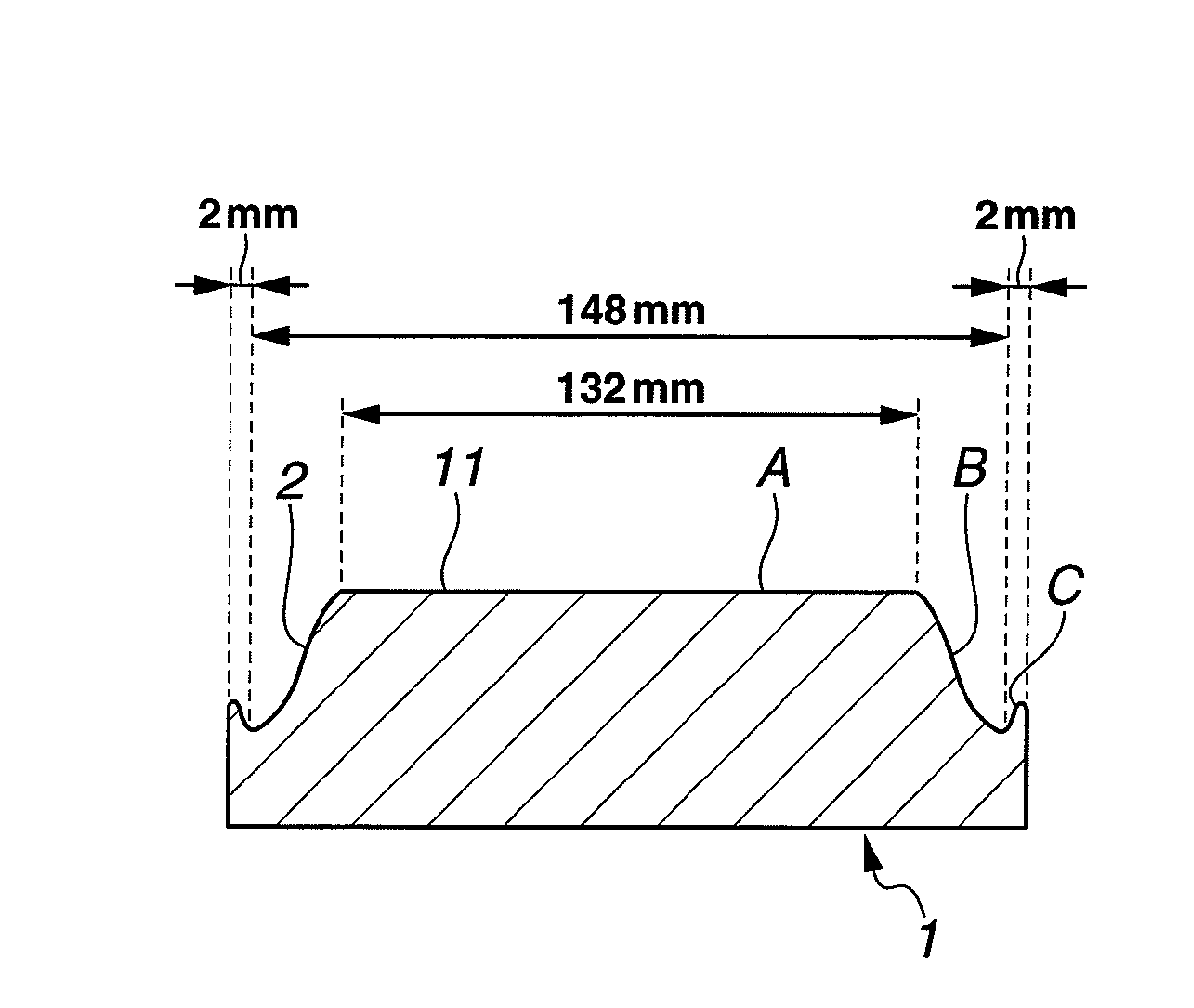
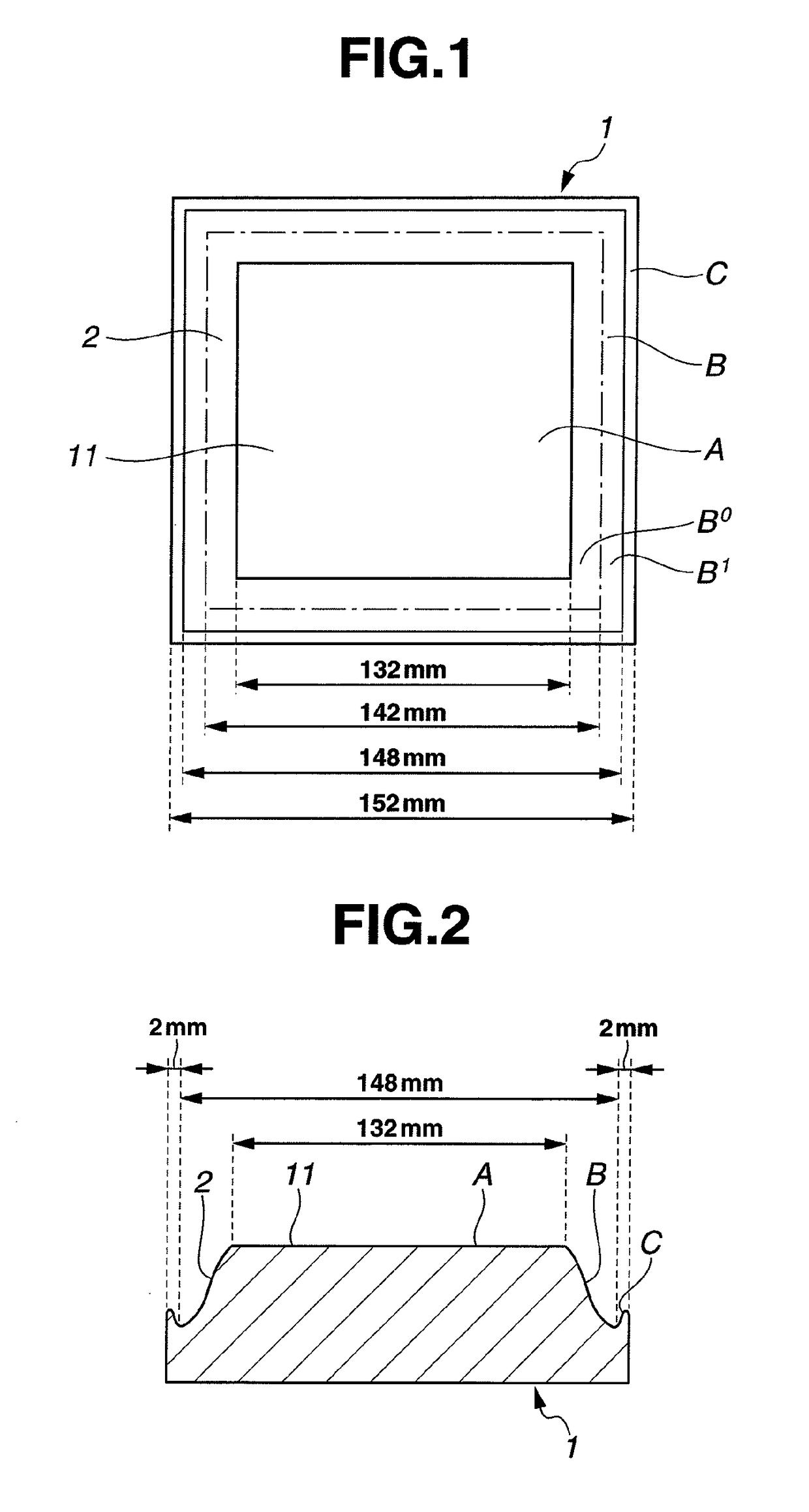
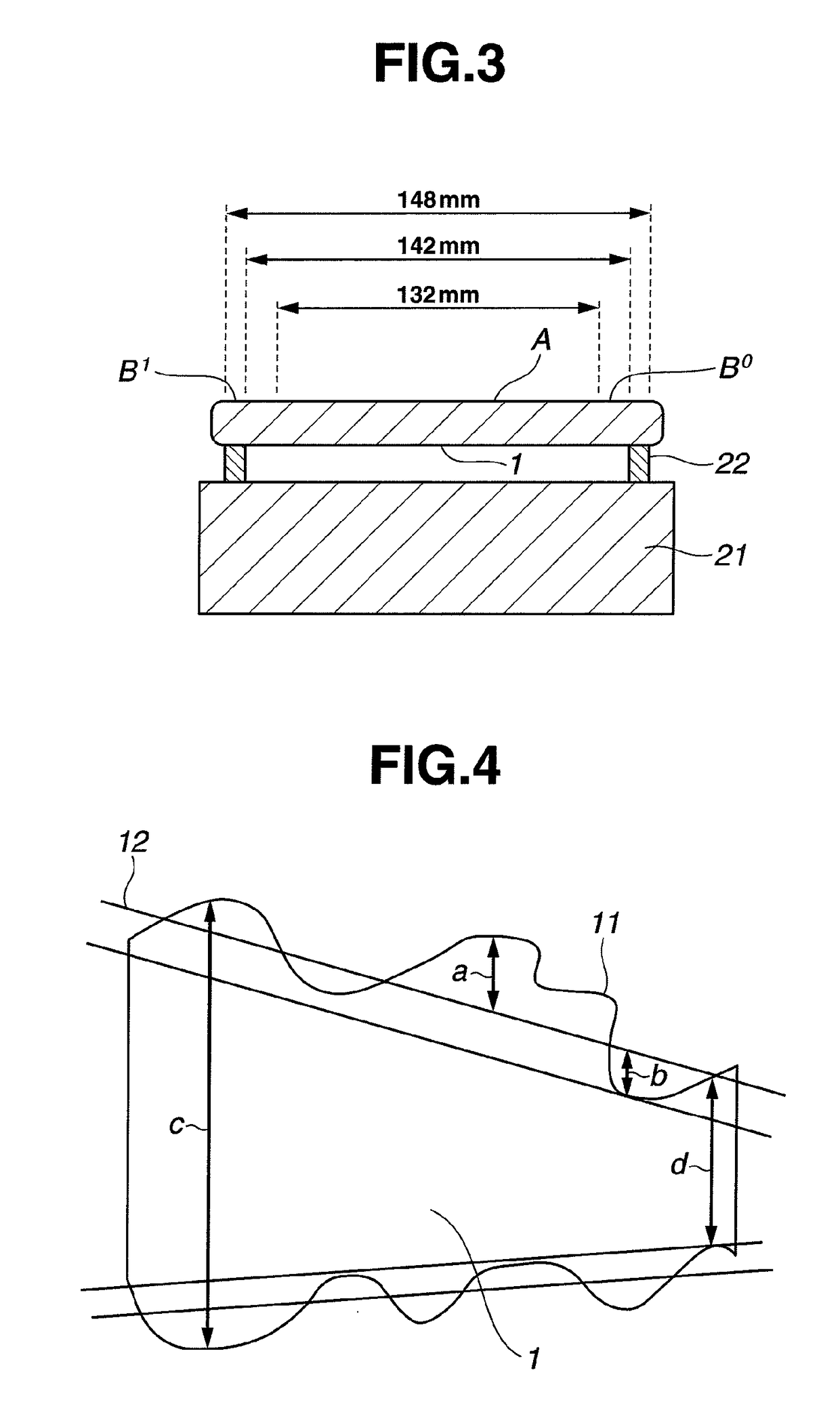
A synthetic quartz glass substrate has a surface of 6 inch squares including a central surface area of 132 mm squares. The central surface area of 132 mm squares has a flatness of up to 50 nm. A frame region obtained by subtracting the central surface area of 132 mm squares from the central surface area of 148 mm squares has a flatness of up to 150 nm.

Description

CROSS-REFERENCE TO RELATED APPLICATION[0001]This non-provisional application claims priority under 35 U.S.C. §119(a) on Patent Application No. 2010-118319 filed in Japan on May 24, 2010, the entire contents of which are hereby incorporated by reference.TECHNICAL FIELD[0002]This invention relates to a synthetic quartz glass substrate suited for use as a photomask, and more particularly, to a synthetic quartz glass substrate whose surface has a high flatness, low defect density, and minimal surface roughness and which is suited for use in the advanced applications of EUV lithography and nano-imprint technology, and a method for preparing the same.BACKGROUND ART[0003]The lithography using radiation of very short wavelength such as soft x-ray makes fine image writing possible at the sacrifice of focal depth. For printing a fine precise pattern, the substrate for the reflective mask is required to meet the completeness of surface parameters including high flatness, low defect density, an...

Claims


Application Information

Patent Timeline
Patent Type & Authority Patents(United States)
IPC IPC(8): B32B3/00B82Y40/00B82Y10/00C03C3/06B24B49/00C03C19/00G03F7/00G03F1/60G03F1/24G03F1/22H01L21/027
CPCC03C3/06B82Y10/00B82Y40/00C03C19/00G03F1/60G03F7/0002C03C2201/42C03C2204/08G03F1/24Y10T428/24355B24B7/242H01L21/0275
Inventor MATSUI, HARUNOBUHARADA, DAIJITSUTAKEUCHI, MASAKI
Owner SHIN ETSU CHEM IND CO LTD
Features
  • Generate Ideas
  • Intellectual Property
  • Life Sciences
  • Materials
  • Tech Scout
  • Unparalleled Data Quality
  • Higher Quality Content
  • 60% Fewer Hallucinations
Learn More