Multifocal intraocular lens simulator and method of simulating multifocal intraocular lens

a multi-focal intraocular lens and simulator technology, applied in intraocular lenses, medical science, diagnostics, etc., can solve the problems of deterioration in visibility, halo (optical phenomenon) tending to occur around the refractive multifocal intraocular lens, and the disadvantage of highlight glar

Active Publication Date: 2011-04-07
HOYA CORP
View PDF9 Cites 20 Cited by
  • Summary
  • Abstract
  • Description
  • Claims
  • Application Information

AI Technical Summary

Benefits of technology

[0009]The present invention provides a multifocal intraocular lens simulator by which one can actually perceive and experience the effects of a multifocal intraocular lens implantation, the difference between diffractive type and refractive type multifocal intraocular lenses, and also the demerits of a multifocal intraocular lens

Problems solved by technology

However, at least one of the two light converging points is seen as blurred image, so that this blur becomes noise, thus becoming a cause of deterioration in visibility such as contrast, etc.
For instance, the diffractive multifocal intraocular lens has a disadvantage of glare (highlight glare) tending to occur, and the refractive multifocal intraocular lens has a disadvantage of a halo (optical phenomenon) tending to occur around a light (s), especially at night time.
These phenomena are due to side effects of the multifocal intraocular lens implant surgery, so that a normal (healthy) eye does not visually identify such phenomena.
Althoug

Method used


Image

  • Multifocal intraocular lens simulator and method of simulating multifocal intraocular lens
  • Multifocal intraocular lens simulator and method of simulating multifocal intraocular lens
  • Multifocal intraocular lens simulator and method of simulating multifocal intraocular lens

Examples


first embodiment

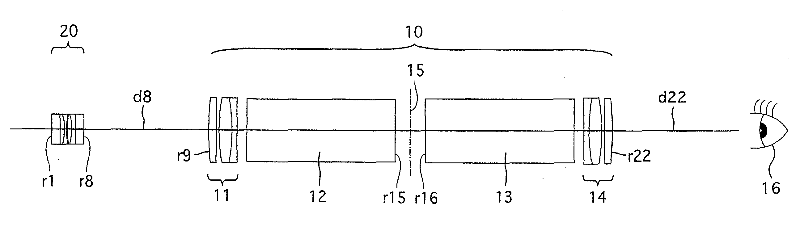
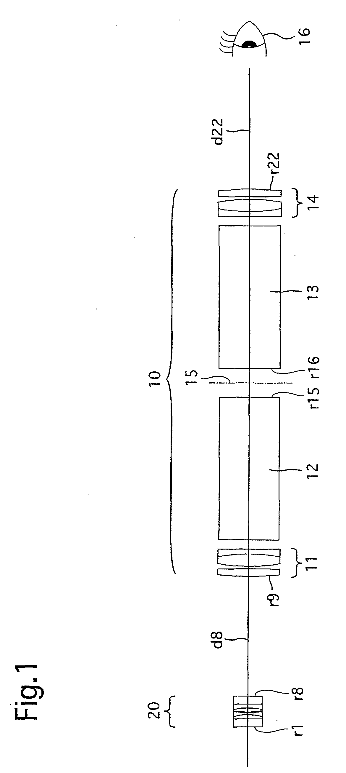
[0066]FIGS. 1 and 2 show an optical system provided in a first embodiment of a multifocal IOL simulator according to the present invention. The optical system of the multifocal IOL simulator is provided with an afocal optical system 10, the angular magnification of which is approximately 1 (1.0×) and an IOL holder (test lens holder) 20 positioned at the entrance pupil of the afocal optical system 10. The afocal optical system 10 is designed such that parallel rays (rays from an infinite object) entering the afocal optical system 10 are also substantially parallel when emerging therefrom.

[0067]The afocal optical system 10 is provided with an objective lens group 11 having positive power, a first prism 12, a second prism 13 and an eyepiece lens group 14 having positive power, in that order from the object side. An image plane 15 is formed between the first prism 12 and the second prism 13. The objective lens group 11 and the first prism 12, and the second prism 13 and the eyepiece len...

numerical embodiment 1

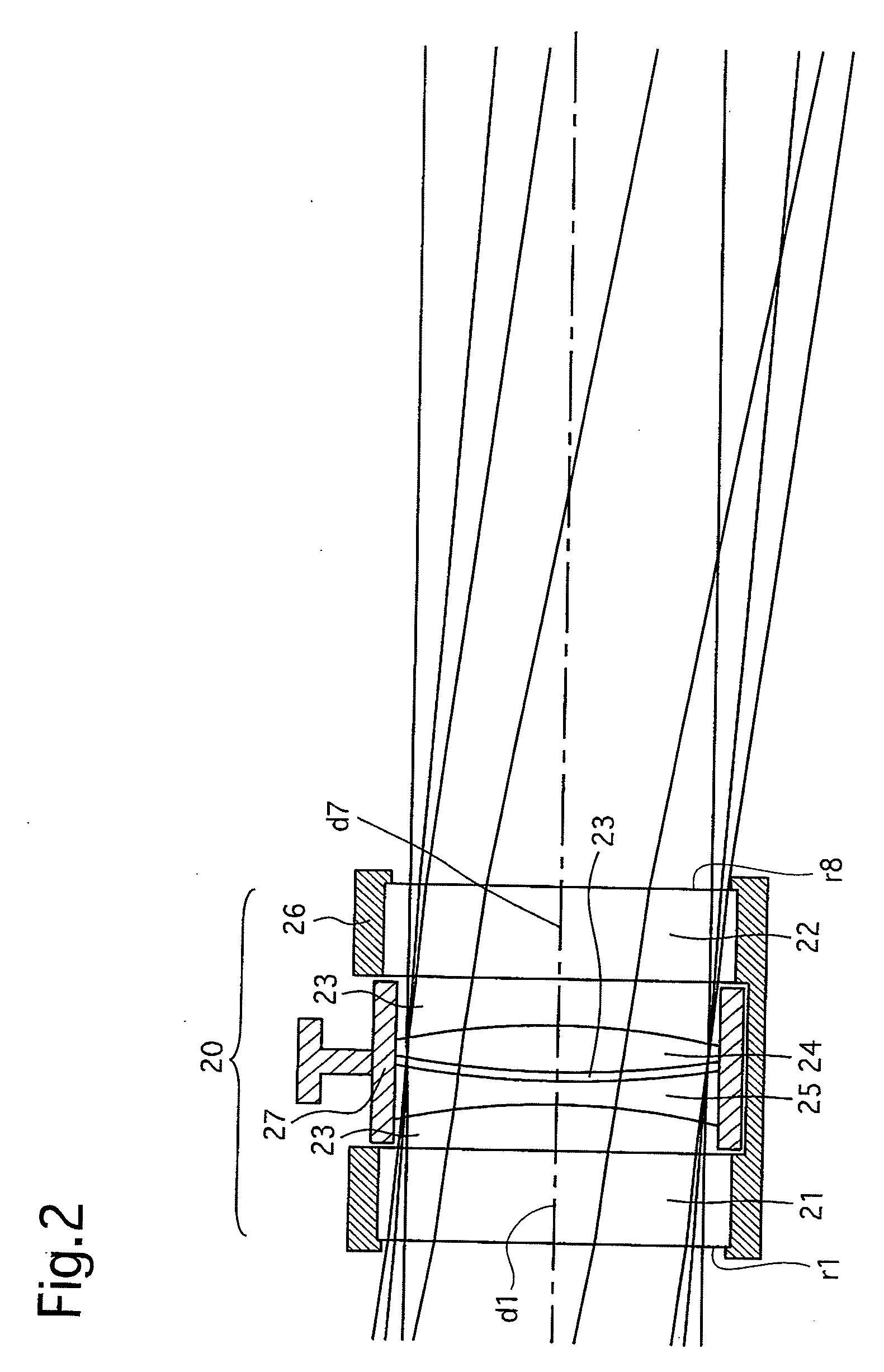
[0072]TABLE 1 below shows lens data in Numerical Embodiment 1 for the optical system shown in FIG. 1. In each of TABLES 1, 2 and 4 through 8, NO designates the surface number counted from the object side, R designates the radius of curvature, d designates the lens-element thickness or the distance between lens elements (lens groups), N(d) designates the refractive index at the d-line, and v designates the Abbe number. The unit of R and the unit of d are mm (millimeters). The surface numbers 1 through 8 designate surfaces of the IOL holder 20 (the surface numbers 5 and 6 designate surfaces of the multifocal IOL 24), and the surface numbers 9 through 22 designate surfaces of the afocal optical system 10. The angle of incidence of light on the IOL holder 20 (angle of incidence of light on the afocal optical system 10) is ±10 degrees.

TABLE 1NORdN(d)ν1∞2.0001.5163364.12∞1.0001.33304(water)55.83−13.650.5001.4917657.4Compensator Lens417.90.2001.33304(water)55.8517.91.0001.4917657.4IOL (20D...

second embodiment

[0074]FIG. 3 shows an optical system provided in a second embodiment of the multifocal IOL simulator according to the present invention. The optical system of this multifocal IOL simulator is provided with an afocal optical system 30, the angular magnification of which is approximately 1 and an IOL holder (test lens holder) 20 positioned at the entrance pupil of the afocal optical system 30. An observer's eye 16 is positioned at the exit pupil of the afocal optical system 30. The IOL holder 20 in the second embodiment of the multifocal IOL simulator is identical to that in the first embodiment of the multifocal TOL simulator.

[0075]The afocal optical system 30 is provided with two Keplerian afocal optical systems 31 and 32 which are symmetrically arranged. In this embodiment, the two Keplerian afocal optical systems 31 and 32 are configured from a pair of binocular optical systems (a pair of erecting binocular telescopes). The Keplerian afocal optical system 31, which is positioned t...


PUM


Abstract

A multifocal intraocular lens simulator includes an optical system enabling an object to be observed therethrough, and a test lens holder which holds a prescribed test intraocular lens. The intraocular lens holder is installed at a position optically conjugate with a position at which an eye of an observer is to be placed. The present invention also teaches a method of simulating a multifocal intraocular lens.

Description

BACKGROUND OF THE INVENTION[0001]1. Field of the Invention[0002]The present invention relates to a multifocal intraocular lens simulator and a method of simulating a multifocal intraocular lens.[0003]2. Description of the Related Art[0004]A cataract surgery treatment, in which the crystalline lens that has developed an opacification is removed and replaced by an intraocular lens (IOL) to restore the lens's transparency, has become a common surgery treatment. On the other hand, multifocal intraocular lenses are used not only for the treatment of cataracts but also for compensating the age-related decline in accommodation ability. The multifocal intraocular lens has different refractive powers: a primary refractive power, and at least one additional refractive power which corresponds to the primary refractive power to which a differential refractive power is added. Two types of the multifocal intraocular lenses are known in the art: a refractive type, and a diffractive type. The refra...

Claims


Application Information

Patent Timeline
IPC IPC(8): A61B3/02
CPCA61B3/0025A61F2/1618A61F2/16A61F2240/008
Inventor IIZUKA, TAKASHIKANAI, MORIYASU
Owner HOYA CORP
Why Eureka
Try Eureka