Translating and Rotation Micro Mechanism

a micro-mechanics and translation technology, applied in the direction of optics, instruments, electrostatic generators/motors, etc., can solve the problems of high power consumption, low accuracy, slow response and low accuracy of electrostatic actuator based designs,

Inactive Publication Date: 2011-04-07
HE SIYUAN +1
View PDF6 Cites 36 Cited by
  • Summary
  • Abstract
  • Description
  • Claims
  • Application Information

AI Technical Summary

Benefits of technology

[0011]Another object of the present invention is to provide a method of operating the translating and rotation mechanism comprising steps of: (a) providing a base; (b) providing a translating and rotation unit; (c) providing two or more bi-directional electrostatic actuators with fixed elements attached onto the base; (d) providing flexible structures elastically connecting the translating and rotation unit to movable elements of each actuator; (e) applying voltages independently to each actuator to drive the translating and rotation unit to translate, or rotate, or translate and rotate simultaneously.

Problems solved by technology

However, electrothermal actuator based designs require high power (10s˜100s mW), are slow to respond and have low accuracy.
Drawbacks of electromagnetic designs include high power consumption, e.g., 100s mW and difficulty in fabrication of the magnetic thin films or the need for an external magnetic field.
However, it is very challenging to achieve a large out-of-plane translation and rotation using electrostatic actuators.

Method used


Image

  • Translating and Rotation Micro Mechanism
  • Translating and Rotation Micro Mechanism
  • Translating and Rotation Micro Mechanism

Examples


Embodiment Construction

[0024]Embodiments herein provide a large stroke out-of-plane translation micro actuator. In the description of the embodiments herein, numerous specific details are provided, such as examples of components and / or mechanisms, to provide a thorough understanding of embodiments herein. One skilled in the relevant art will recognize, however, that an embodiment herein can be practiced without one or more of the specific details, or with other apparatus, systems, assemblies, methods, components, materials, parts, and / or the like. In other instances, well-known structures, materials, or operations are not specifically shown or described in detail to avoid obscuring aspects of embodiments herein.

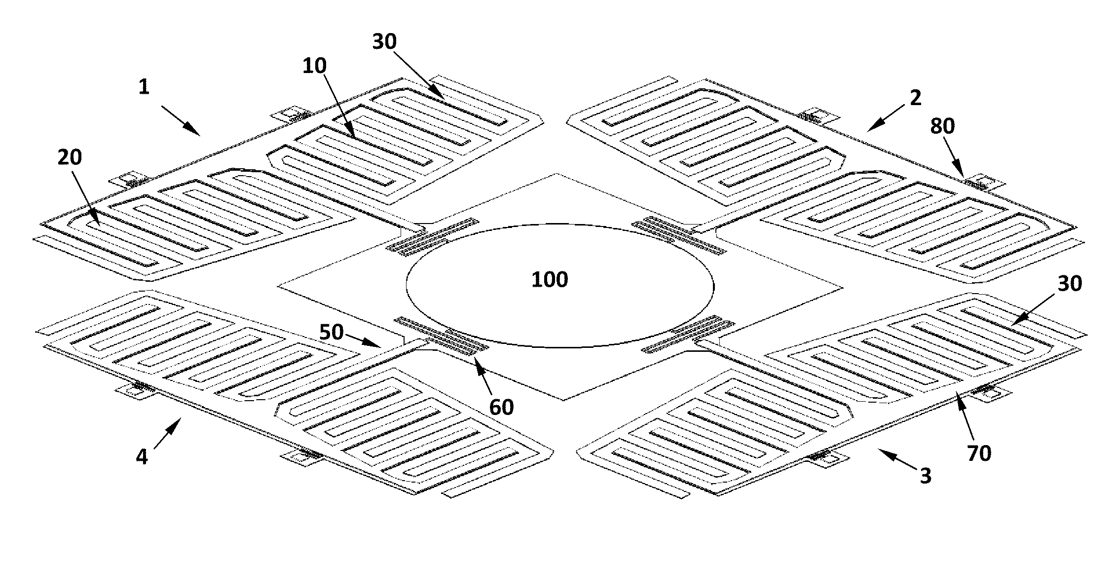
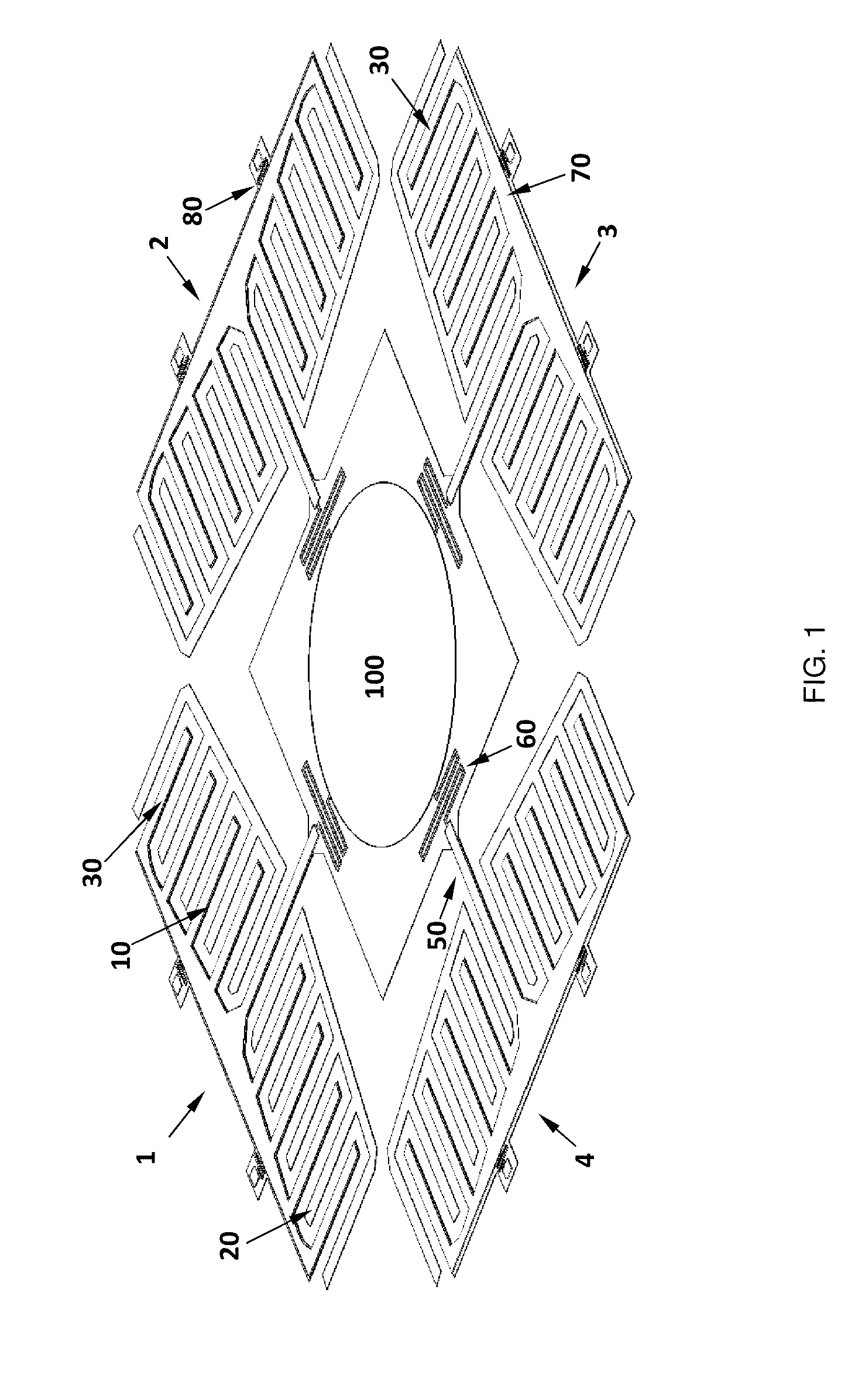
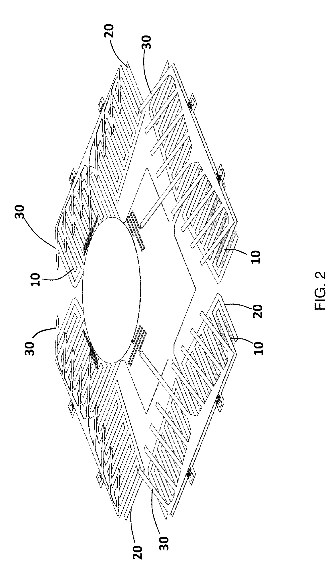
[0025]One embodiment of the large stroke out-of-plane translation micro actuator disclosed here (see FIGS. 1 and 2) is comprised of a central translating unit 100 and four of repulsive-force rotation actuators, 1, 2, 3, and 4, which are referred to as rotation driving units. The number of the rotat...


PUM


Abstract

A translation and rotation mechanism is disclosed, which comprises of one or more bi-directional electrostatic actuators. Each bi-directional electrostatic actuator comprising of fixed electrodes and movable electrodes, where the fixed electrodes of each actuator being attached onto a base. The movable electrodes of each actuator are connected to the translating and rotation unit through a spring system. The movable elements of each said actuator being able to rotate with respect to the base plane by applying voltage signals to the actuator and by controlling the voltage signals applied to each said actuator independently, said translating and rotation unit being able to translate, rotate, or translate and rotate simultaneously.

Description

CROSS REFERENCE TO THE RELATED APPLICATION[0001]This application claims the benefit of the earlier filed U.S. Provisional patent application, with application No. 61 / 248,004, file on Oct. 2, 2009, the entire contents of which are herein incorporated by reference.FIELD OF THE INVENTION[0002]The present invention relates to the field of micro translating and rotation mechanisms and Micro Optical Electro Mechanical Systems (MOEMS).BACKGROUND OF THE INVENTION[0003]Translating and rotation micro mechanisms can be used in many applications such as adaptive optics for wavefront corrections, spatial light modulation, micro endoscopic confocal imaging, positioning micro lenses for auto focusing / zooming, aligning optical components, micromanipulators or micro stages. Most of these applications require a large out-of-plane translation or rotation or both, e.g., more than 10 μm is needed for adaptive optics modules used in large size ground telescopes, more than 20 μm is needed for wavefront co...

Claims


Application Information

Patent Timeline
Patent Type & Authority Applications(United States)
IPC IPC(8): G02B26/08
CPCB81B3/0062B81B2201/042G02B26/101B81B2203/058G02B26/0841B81B2203/053
Inventor HE, SIYUANBENMRAD, RIDHA
Owner HE SIYUAN
Why Eureka
Try Eureka