Ground fault sensing device

a ground fault and sensing device technology, applied in electric devices, lighting and heating devices, instruments, etc., can solve the problems of difficult ground fault detection on the electric motor side, alternating current side, etc., and achieve the effect of simple and easy manner

Active Publication Date: 2011-04-07
HITACHI ASTEMO LTD
View PDF6 Cites 31 Cited by
  • Summary
  • Abstract
  • Description
  • Claims
  • Application Information

AI Technical Summary

Benefits of technology

[0018]According to the present invention, it is possible to detect a ground fault on the alternating current side in a simple and easy manner.

Problems solved by technology

However since, with the method disclosed in Patent Document #1, it is arranged to detect the occurrence of a ground fault on the battery side (i.e. the direct current side), accordingly it is difficult to detect the occurrence of a ground fault on the electric motor side (i.e. the alternating current side).
Furthermore, sometimes it may happen that the ground fault determination described above becomes difficult if a ground fault has occurred upon the alternating current side, because an amplitude wave corresponding to the rotation speed of the electric motor is superimposed via the Y-capacitor upon the periodic waveform.

Method used


Image

  • Ground fault sensing device
  • Ground fault sensing device
  • Ground fault sensing device

Examples


first embodiment

The First Embodiment

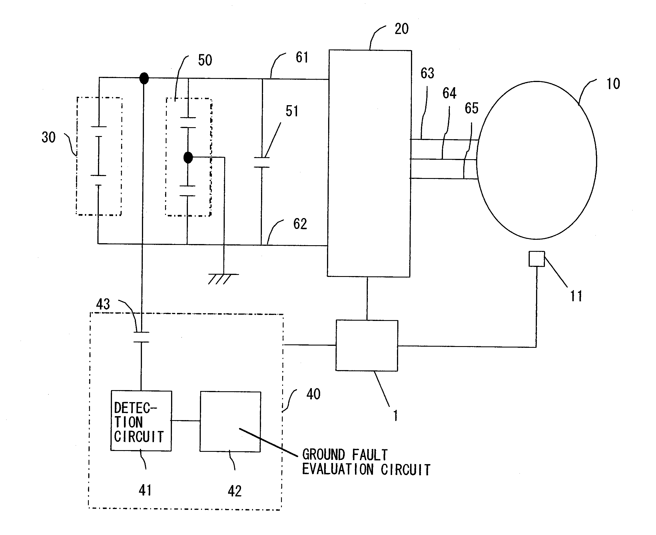
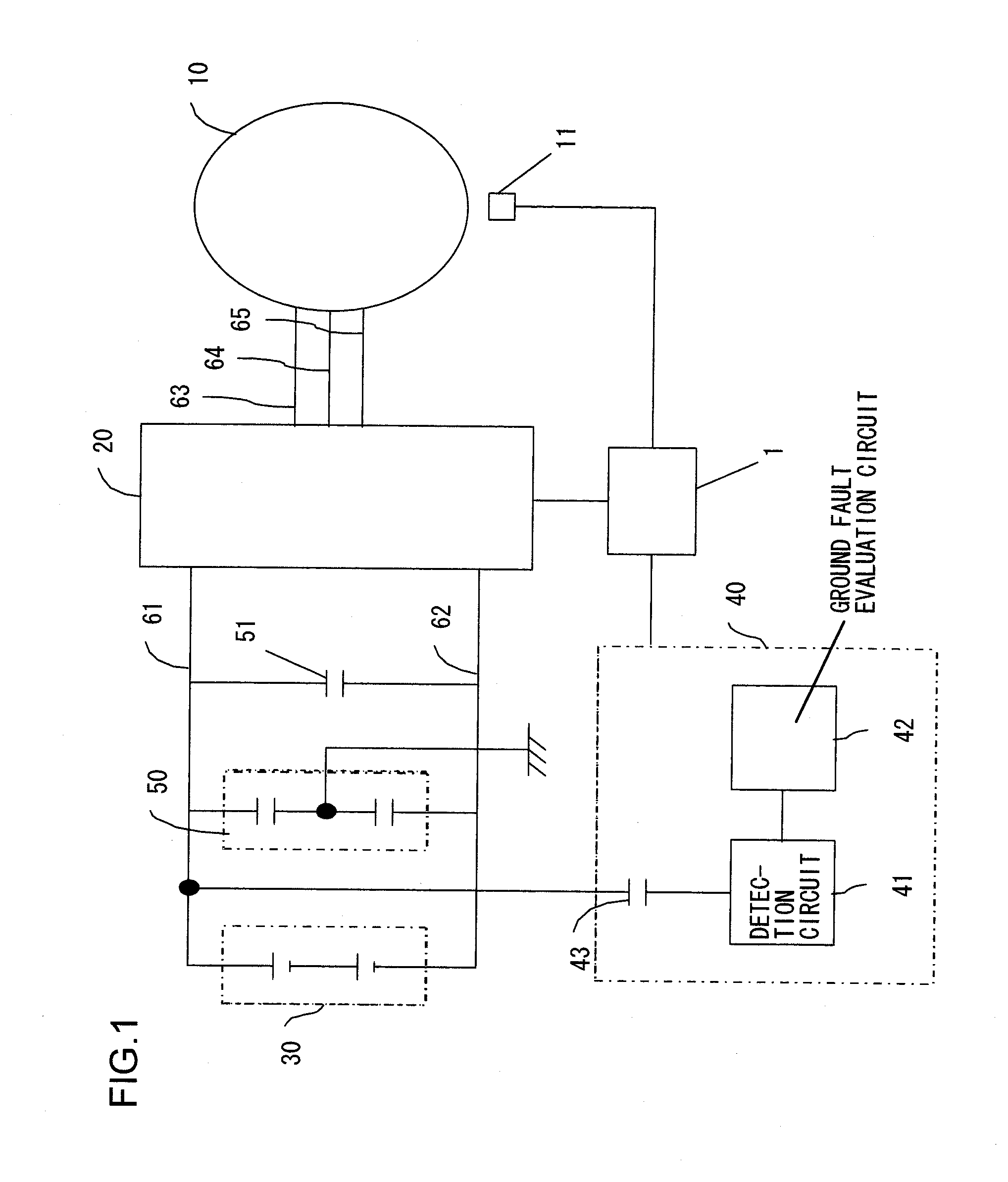
[0030]FIG. 1 is a figure for explanation of a first embodiment of the ground fault sensing device of the present invention. Here, an example will be explained of a ground fault sensing device for a vehicle drive system in which an electric motor is driven by a battery via an inverter. It should be understood that ground fault sensing for the electric motor side (i.e. for the alternating current side) by this first embodiment will be explained.

[0031]This drive system includes a main controller 1, a three-phase alternating current electric motor 10 (hereinafter termed the “electric motor”), an inverter 20, a battery 30 that serves as a direct current power supply, and a ground fault sensing device 40. The battery 30 is a battery group that provides a high voltage direct current power supply (the output voltage VB may, for example, be 340 V), and this battery is electrically insulated from the body of the vehicle (not shown in the figures). The battery 30 and the in...

second embodiment

The Second Embodiment

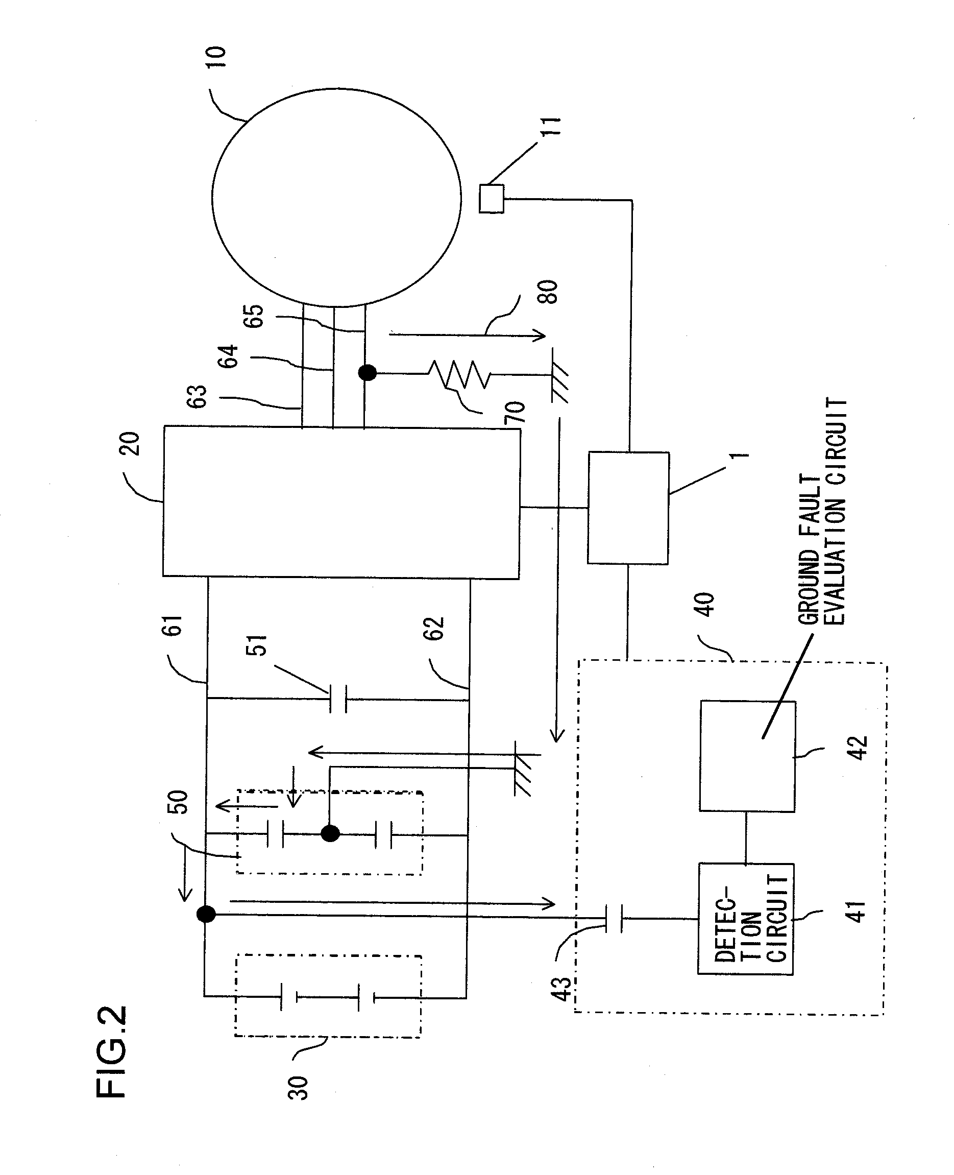
[0046]FIG. 6 is a figure for explanation of a second embodiment of the ground fault sensing device of the present invention. This ground fault sensing device 40 includes a detection circuit 41, a ground fault evaluation circuit 42, a coupling capacitor 43, and a waveform output circuit 44. While in the first embodiment a ground fault sensing device was explained that detects the occurrence of a ground fault on the electric motor side, in this second embodiment, a structure is provided that is able to detect both the occurrence of a ground fault on the electric motor side (i.e. the alternating current side), and also the occurrence of a ground fault on the battery side (i.e. the direct current side). Due to this, this detection circuit includes both a circuit that handles the occurrence of a ground fault on the electric motor side, and also a circuit that handles the occurrence of a ground fault on the battery side.

[0047]FIG. 7 is a figure showing an example of t...


PUM


Abstract

A ground fault sensing device for a drive system that converts direct current electrical power from a direct current power supply into alternating current electrical power and drives an electric motor with that alternating current electrical power, comprises: an extraction circuit that is connected to a power supply line of the direct current power supply via a coupling capacitor, that detects an amplitude wave that is generated when an alternating current side including the electric motor is suffering a ground fault, and that extracts the envelope of the amplitude wave; a measurement circuit that measures the voltage level of the envelope; and a determination circuit that makes a decision as to whether or not a ground fault has occurred on the alternating current side by comparing together the voltage level measured by the measurement circuit and a ground fault decision value.

Description

INCORPORATION BY REFERENCE[0001]The disclosure of the following priority application is herein incorporated by reference: Japanese Patent Application No. 2009-232283 filed Oct. 6, 2009BACKGROUND OF THE INVENTION[0002]1. Field of the Invention[0003]The present invention relates to a ground fault sensing device.[0004]2. Description of Related Art[0005]Since, in an electric vehicle or a hybrid electric vehicle, a high voltage battery is provided for operating devices such as an electric motor and an inverter, accordingly it is necessary to provide a ground fault sensing means for protecting the personnel riding in the vehicle from this high voltage. Due to this, technical standards have been determined for protecting the personnel riding in the vehicle from high voltage. For example, it has been made a requirement to install a device that monitors the insulation resistance between the active electrode and the electrical chassis, and that issues a warning to the driver when the value of...

Claims


Application Information

Patent Timeline
Patent Type & Authority Applications(United States)
IPC IPC(8): H02H7/08
CPCG01R31/025G01R31/007B60L3/0061B60L3/12B60L2240/421G01R31/52Y02T10/64
Inventor YOSHIDA, TAKESHIYANAI, TAKAO
Owner HITACHI ASTEMO LTD
Why Eureka
Try Eureka