Devices and Methods for Tissue Engineering

a tissue engineering and device technology, applied in the field of porous medical implants, can solve the problems of increased infection risk, unnecessary pain and discomfort at the harvest site, disease transmission, immune reactions,

Inactive Publication Date: 2011-04-07
BIO2 TECH
View PDF44 Cites 33 Cited by
  • Summary
  • Abstract
  • Description
  • Claims
  • Application Information

AI Technical Summary

Benefits of technology

[0007]The present invention meets the objectives of an effective synthetic bone prosthetic for the repair of bone defects by providing a scaffold that is osteostimulative, and load bearing with mechanical properties that match the living tissue at the implant site. The present invention provides a tissue scaffold of bioinert metal fiber with specific pore morphology and sintered to form a rigid three dimensional porous matrix having a bioinert composition. The porous matrix has interconnected pore space having a pore size distribution determined by volatile components present before the bioinert metal fibers are bonded together. In an embodiment the porous matrix has a pore size distribution in the range of about 50 μm to about 600 μm. The porous matrix can have a porosity between 40% and 85% to provide osteoconductivity once implanted in bone tissue. Embodiments of the present invention include pore space having a bi-modal pore size distribution, or a multi-modal pore size distribution.

Problems solved by technology

However, autografting procedures are particularly invasive, causing risk of infection and unnecessary pain and discomfort at the harvest site.
In allografting procedures, bone grafts are used from a donor of the same species but the use of these materials can raise the risk of infection, disease transmission, and immune reactions, as well as religious objections.
Materials developed to date have been successful in attaining at least some of the desired characteristics, but nearly all materials compromise at least some aspect of the bio-mechanical requirements of an ideal hard tissue scaffold.

Method used


Image

  • Devices and Methods for Tissue Engineering
  • Devices and Methods for Tissue Engineering
  • Devices and Methods for Tissue Engineering

Examples


examples

[0082]The following examples are provided to further illustrate and to facilitate the understanding of the disclosure. These specific examples are intended to be illustrative of the disclosure and are not intended to be limiting in an way.

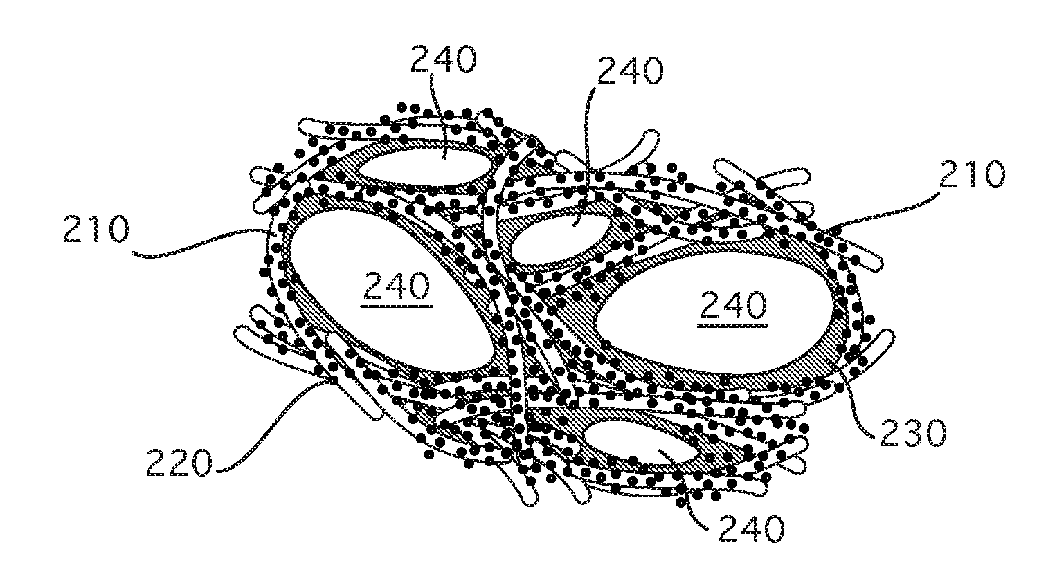
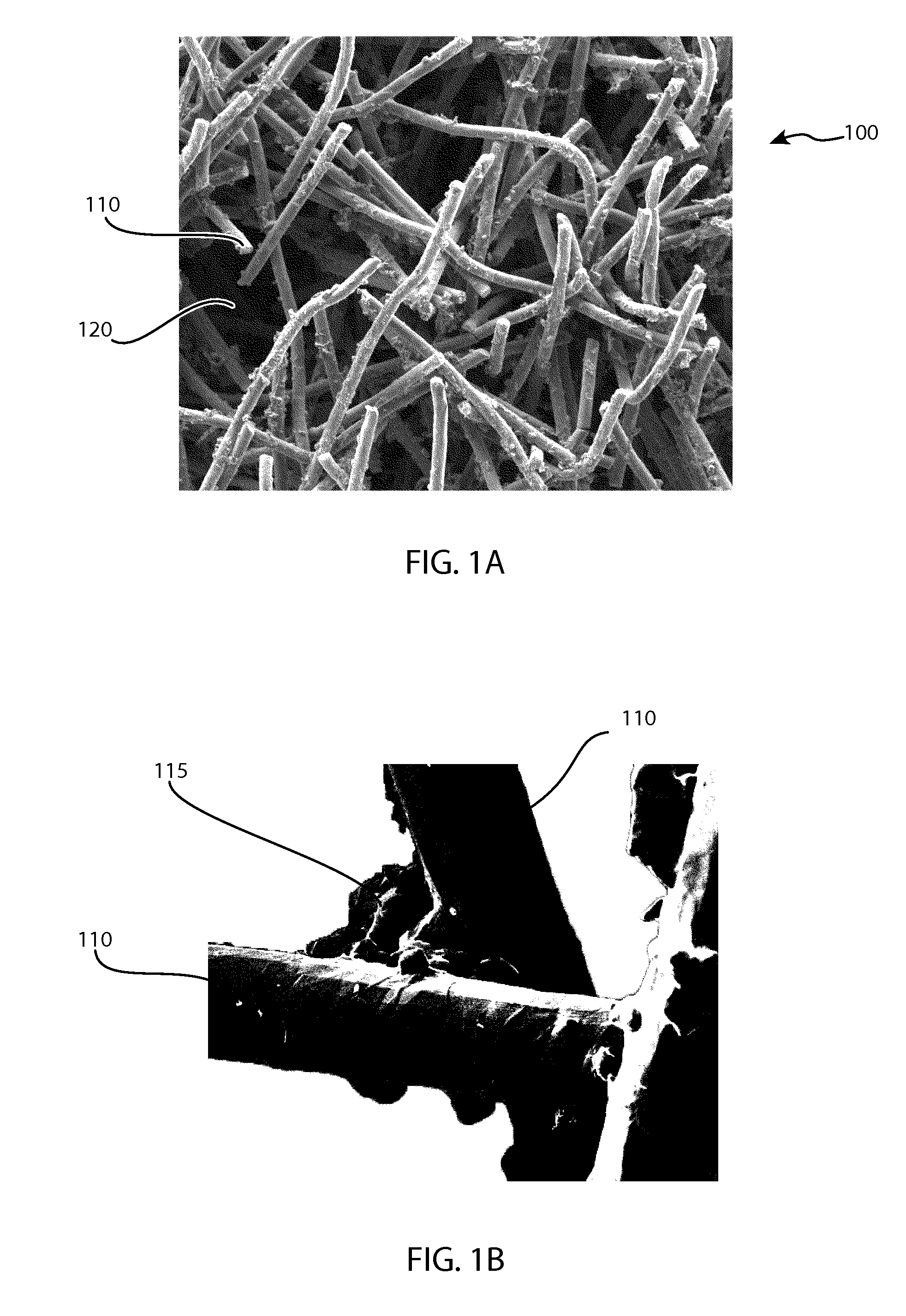
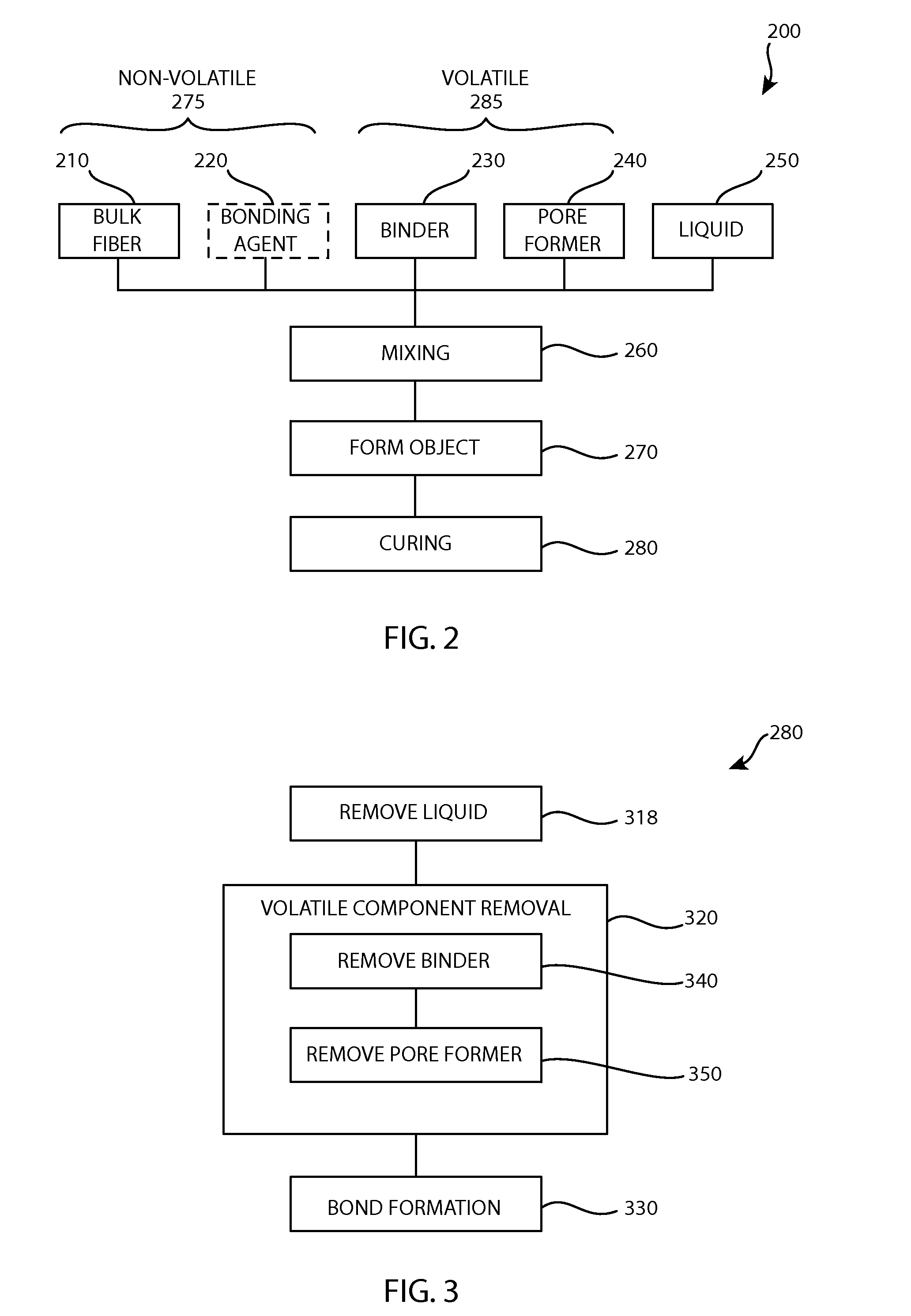
[0083]In a first exemplary embodiment a scaffold is formed from titanium fiber by mixing 4 grams of titanium 6A14V alloy fiber having an average diameter of approximately 225 μm chopped into lengths of approximately 1 to 3 mm, in bulk form, as the non-volatile components with 0.125 gram of HPMC as an organic binder and 0.5 grams of PMMA with a particle size of 25-30 μm as a pore former and approximately 1.5 grams of deionized water, adjusted as necessary to provide a plastically formable mixture. The mixture was extruded into a 10 mm diameter rod and dried in a convection oven. The volatile components were burned out and then heat treated at 1,400° C. at 0.3 torr vacuum for two hours. The porosity for this example was measured to be 69.1%.

[0084]In ...


PUM

PropertyMeasurementUnit
pore size distributionaaaaaaaaaa
diameteraaaaaaaaaa

Abstract

A tissue scaffold fabricated from bioinert fiber forms a rigid three-dimensional porous matrix having a bioinert composition. Porosity in the form of interconnected pore space is provided by the space between the bioinert fiber in the porous matrix. Strength of the porous matrix is provided by bioinert fiber fused and bonded into the rigid three-dimensional matrix having a specific pore size and pore size distribution. The tissue scaffold supports tissue in-growth to provide osteoconductivity as a tissue scaffold, used for the repair of damaged and / or diseased bone tissue.

Description

CROSS-REFERENCE TO RELATED APPLICATIONS[0001]This application claims the benefit of Provisional Application No. 61 / 249,449 filed Oct. 7, 2009, and Provisional Application No. 61 / 306,136 filed Feb. 19, 2010, and Provisional Application No. 61 / 381,666 filed Sep. 10, 2010, each of which are herein incorporated by reference.FIELD OF THE INVENTION[0002]The present invention relates generally to the field of porous medical implants. More specifically, the invention relates to a bioinert fibrous implant having osteostimulative properties in applications of in vivo environments.BACKGROUND OF THE INVENTION[0003]Prosthetic devices are often required for repairing defects in bone tissue in surgical and orthopedic procedures. Prostheses are increasingly required for the replacement or repair of diseased or deteriorated bone tissue in an aging population and to enhance the body's own mechanism to produce rapid healing of musculoskeletal injuries resulting from severe trauma or degenerative disea...

Claims


Application Information

Patent Timeline
Patent Type & Authority Applications(United States)
IPC IPC(8): A61F2/02B05D1/18
CPCA61F2/28A61F2/3094A61F2/4465A61F2002/2892A61F2002/30062A61F2002/3092A61L27/56A61F2002/4495A61F2310/00329A61L27/04A61L27/10A61L27/12A61F2002/30968A61L27/42A61L27/06A61L27/02
Inventor LIU, JAMES JENQWALLEN, ADAMNUUTINEN, JUHA-PEKKA
Owner BIO2 TECH
Why Eureka
Try Eureka