Electrolyte Concentration Control System for High Rate Electroplating

a technology of electroplating control and electroplating metals, applied in the direction of electrolysis process, electrolysis components, tanks, etc., can solve the problems of difficult deposition of copper into such structures, limited step coverage, and high cost of precursors, and achieve the effect of increasing the formation of voids and increasing the plating ra

Active Publication Date: 2011-04-14
NOVELLUS SYSTEMS
View PDF16 Cites 36 Cited by
  • Summary
  • Abstract
  • Description
  • Claims
  • Application Information

AI Technical Summary

Benefits of technology

[0006]It is herein provided that the use of commercially available electrolytes which are unsaturated at 0° C., results in plating rates which may be unacceptably slow (e.g., an hour or more for TSV fill), and may also be associated with increased formation of voids during TSV filling.

Problems solved by technology

TSV holes typically have high aspect ratios making void-free deposition of copper into such structures a challenging task.
CVD deposition of copper requires complex and expensive precursors, while PVD deposition often results in voids and limited step coverage.
Electroplating is a more common method of depositing copper into TSV structures; however, electroplating also presents a set of challenges because of the TSV's large size and high aspect ratio.
However, the use of standard commercially available electrolytes often results in very slow plating and in formation of voids during TSV filling.
It is herein provided that the use of commercially available electrolytes which are unsaturated at 0° C., results in plating rates which may be unacceptably slow (e.g., an hour or more for TSV fill), and may also be associated with increased formation of voids during TSV filling.

Method used


Image

  • Electrolyte Concentration Control System for High Rate Electroplating
  • Electrolyte Concentration Control System for High Rate Electroplating
  • Electrolyte Concentration Control System for High Rate Electroplating

Examples


example

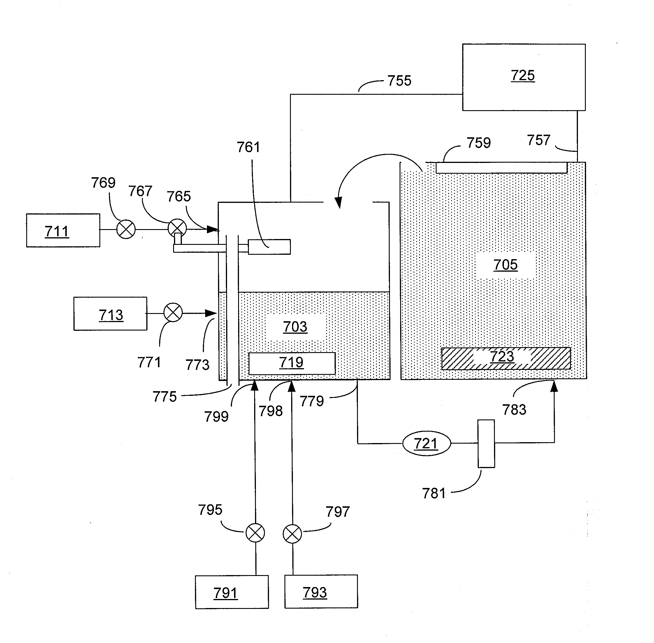
[0099]In one illustrative example, a solution containing copper sulfate at Cu2+ concentration of between about 65-85 g / L is directed from source 791 to the reservoir 703. The solution in the reservoir is heated to a temperature of about 35° C., and then sulfuric acid having a concentration of between about 900-1800 g / L is added to the reservoir and is mixed with the solution of copper sulfate to form a concentrated solution having 60-80 g / L Cu2+ and between about 5-50 g / L sulfuric acid. The resulting concentrated solution is directed to the plating cell 705, where copper is electrodeposited on the substrate at a temperature of about 30-35° C.

[0100]Although various details have been omitted for clarity's sake, various design alternatives may be implemented. Therefore, the present examples are to be considered as illustrative and not restrictive, and the invention is not to be limited to the details given herein, but may be modified within the scope of the appended claims. For example...


PUM

PropertyMeasurementUnit
temperatureaaaaaaaaaa

Abstract

An electroplating apparatus for filling recessed features on a semiconductor substrate includes an electrolyte concentrator configured for concentrating an electrolyte having Cu2+ ions to form a concentrated electrolyte solution that would have been supersaturated at 20° C. The electrolyte is maintained at a temperature that is higher than 20° C., such as at least at about 40° C. The apparatus further includes a concentrated electrolyte reservoir and a plating cell, where the plating cell is configured for electroplating with concentrated electrolyte at a temperature of at least about 40° C. Electroplating with electrolytes having Cu2+ concentration of at least about 60 g/L at temperatures of at least about 40° C. results in very fast copper deposition rates, and is particularly well-suited for filling large, high aspect ratio features, such as through-silicon vias.

Description

FIELD OF THE INVENTION[0001]The present invention relates generally to methods and apparatus for electrodepositing metals on semiconductor substrates having recessed features and more particularly to methods and apparatus for electroplating copper for filling through silicon vias (TSVs).BACKGROUND OF THE INVENTION[0002]A TSV is a vertical electrical connection passing completely through a silicon wafer or die. TSV technology is important in creating 3D packages and 3D integrated circuits (IC). It provides interconnection of vertically aligned electronic devices through internal wiring that significantly reduces complexity and overall dimensions of a multi-chip electronic circuit.[0003]A typical TSV process involves forming TSV holes and depositing conformal diffusion barrier and conductive seed layers, followed by filling of TSV holes with a metal. Copper is typically used as the conductive metal in TSV fill as it supports high current densities experienced at complex integration, s...

Claims


Application Information

Patent Timeline
Patent Type & Authority Applications(United States)
IPC IPC(8): C25D21/18C25D7/12C25D17/02
CPCC25D3/38C25D17/00C25D21/02C25D17/001C25D21/18C25D7/123C25D21/14
Inventor REID, JONATHAN D.VARADARAJAN, SESHASAYEEMAYER, STEVEN T.
Owner NOVELLUS SYSTEMS
Why Eureka
Try Eureka