
Water purifier and water purification method

Inactive Publication Date: 2011-04-14
FUJIFILM CORP
View PDF1 Cites 19 Cited by
  • Summary
  • Abstract
  • Description
  • Claims
  • Application Information

AI Technical Summary

Benefits of technology

[0015]The present invention aims at providing a water purifier capable of reducing inner pressure thereof without any special power, capable of efficiently providing highly purified water, and having excellent cooling effects, as well as providing a water purification method using the same.
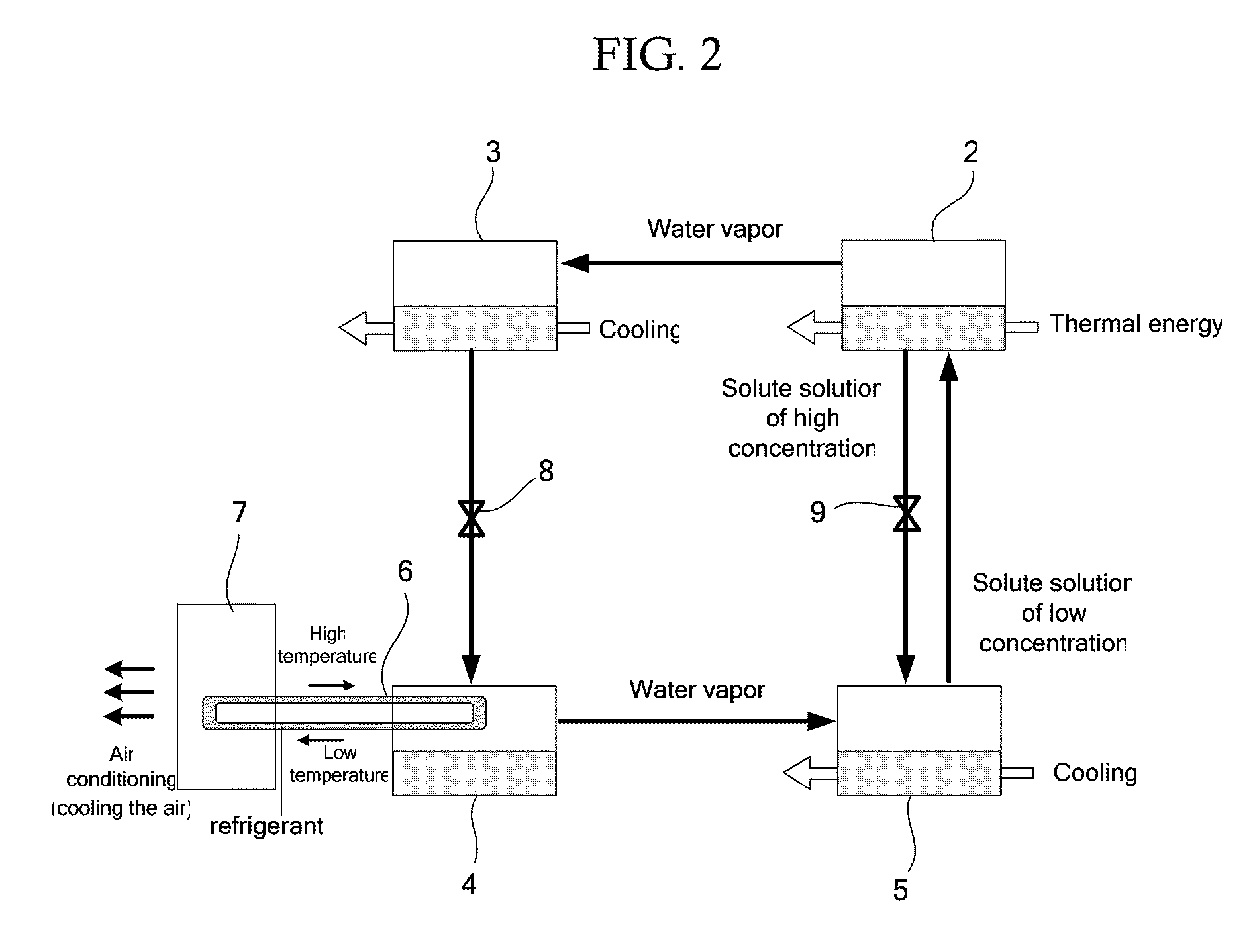
[0028]The absorbing unit is configured to allow the concentrated nonvolatile compound-containing aqueous solution obtained by the separating unit to absorb the water vapor obtained by the evaporating unit. As a result, the inner atmosphere of the system can be kept in the reduced pressure without using any special power, and highly purified water can be efficiently obtained.
[0031]Moreover, as the nonvolatile compound-containing aqueous solution is circulated between the separating unit and the absorbing unit with its concentration changing, highly purified water can very efficiently obtained.
[0040]In the water purifier according to <6>, the evaporating unit contains the cooling pipe, in which the refrigerant is circulated, and the refrigerant within the cooling pipe is cooled by vaporization heat generated at the time when the water is evaporated in the evaporating unit. Therefore, air conditioning can be performed for cooling the air using the cooled refrigerant, and in such manner, a conventional absorption cooling system can be effectively used.
[0056]The absorbing step is allowing the concentrated nonvolatile compound-containing aqueous solution to absorb the obtained water vapor. As a result, the inner atmosphere of the system can be kept in the reduced pressure without using any special power, and highly purified water can be efficiently obtained.
[0057]The present invention solves the various problems in the art, and can provide a water purifier capable of reducing inner pressure thereof without any special power, capable of efficiently providing highly purified water, and having excellent cooling effects, as well as providing a water purification method using the same.

Problems solved by technology

Hence, there is a possibility that the purified water may be contaminated by the residual volatile ions, which has not been completely separated.
However, the entire water in the system needs to be circulated, and there is no intention to collect purified water.

Method used


Image

  • Water purifier and water purification method
  • Water purifier and water purification method
  • Water purifier and water purification method

Examples


example 1

[0112]Example 1 of the present invention will be explained hereinafter.

[0113]FIG. 3 is a schematic diagram showing Example 1 of the water purifier.

[0114]The water purifier 100 of Example 1 contains a diluting unit 1, a separating unit 2, a condensing unit 3, an evaporating unit 4, and an absorbing unit 5.

[0115]In this water purifier 100 of Example 1, sea-water is used as targeted water.

[0116]The diluting unit 1 is a unit which brings the targeted water into contact with a nonvolatile compound-containing aqueous solution via a semi-permeable membrane 11 to separate water from the targeted water, and dilutes the nonvolatile compound-containing aqueous solution with the water separated from the targeted water by the semi-permeable membrane. The diluting unit 1 is connected to the separating unit 2.

[0117]The diluting unit 1 is disposed between the separating unit 2 and the absorbing unit 5.

[0118]The diluting unit 1 is constructed so that the nonvolatile compound-containing aqueous solut...


PUM

PropertyMeasurementUnit
Pressureaaaaaaaaaa
Pressureaaaaaaaaaa
Pressureaaaaaaaaaa

Abstract

To provide a water purifier containing: a diluting unit configured to bring targeted water into contact with a nonvolatile compound-containing aqueous solution via a semi-permeable membrane to separate water from the targeted water by the membrane, and to dilute the nonvolatile compound-containing aqueous solution with the separated water; a separating unit configured to heat the diluted aqueous solution so as to separate water vapor from the diluted aqueous solution, and to obtain the concentrated aqueous solution; a condensing unit configured to cool the separated water vapor to generate water; an evaporating unit configured to collect, as purified water, part of the generated water, and to evaporate the rest of the generated water under the reduced pressure to obtain water vapor; and an absorbing unit configured to allow the concentrated aqueous solution obtained by the separating unit to absorb the water vapor obtained by the evaporating unit.

Description

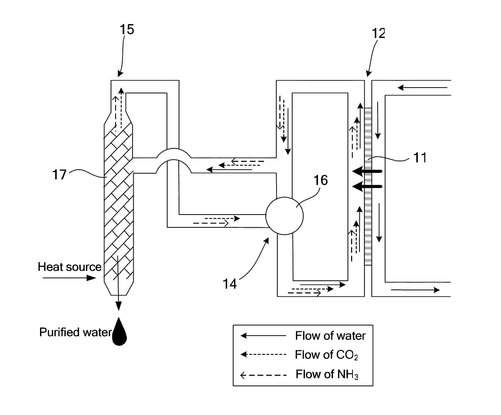
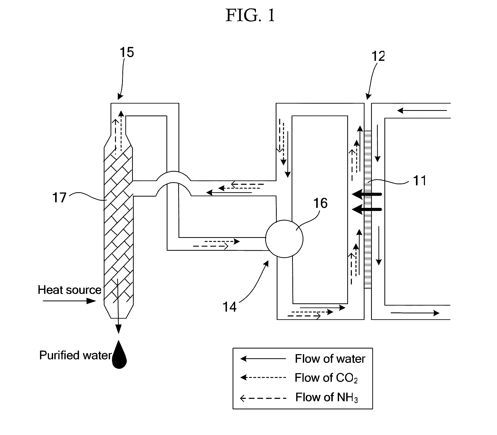
BACKGROUND OF THE INVENTION [0001]1. Field of the Invention[0002]The present invention relates to a water purifier capable of reducing inner pressure thereof without any special power, capable of efficiently providing highly purified water, and having excellent cooling effects. The present invention also relates to a water purification method using the same.[0003]2. Description of the Related Art[0004]A reverse osmosis (RO) process using external pressure and a forward osmosis (FO) process have been known as a method for selectively separating and transferring water between two solutions having mutually different osmotic pressures.[0005]One example of the forward osmosis processes is a method using a volatile ion-containing solution including volatile anions and volatile cations. For example, in US Patent Application Publication No. 2005 / 0145568, there has been proposed a water purifying device containing: a diluting unit 12 configured to bring targeted water into contact with a vol...

Claims


Application Information

Patent Timeline
IPC IPC(8): C02F1/04C02F1/42B01D3/34B01D61/00
CPCB01D5/006B01D61/002C02F2209/05C02F5/08C02F1/445C02F1/44C02F1/16B01D2311/06C02F1/04C02F1/14B01D2311/2673B01D2311/2626B01D2311/2669Y02W10/37
Inventor TOMINAGA, JOIKEDA, MORIHITOMOGI, FUMIOMIYAMOTO, KIMIAKI
Owner FUJIFILM CORP
Learn More