Imprint apparatus and manufacturing method of commodities

a technology of imprinting apparatus and manufacturing method, which is applied in the direction of photomechanical apparatus, instruments, applications, etc., can solve the problems of affecting the quality of imprinting, so as to prevent the degradation of overlay accuracy of a pattern and the excellent demolding process

Inactive Publication Date: 2011-04-14
CANON KK
View PDF2 Cites 3 Cited by
  • Summary
  • Abstract
  • Description
  • Claims
  • Application Information

AI Technical Summary

Benefits of technology

[0009]The present invention provides a technique for preventing degradation of overlay accuracy of a pattern caused by the drive of a stage and capable of executing an excellent demolding process.

Problems solved by technology

The vibration of the structure frame causes relative vibration of the wafer and the mold, and overlay accuracy of the pattern formed on the substrate is degraded.
However, as demolding force is provided to the mold during demolding, force generated in the structure is propagated to the anti-vibration mount with low supporting rigidity.
As a result, excellent demolding cannot be performed.

Method used


Image

  • Imprint apparatus and manufacturing method of commodities
  • Imprint apparatus and manufacturing method of commodities
  • Imprint apparatus and manufacturing method of commodities

Examples


first embodiment

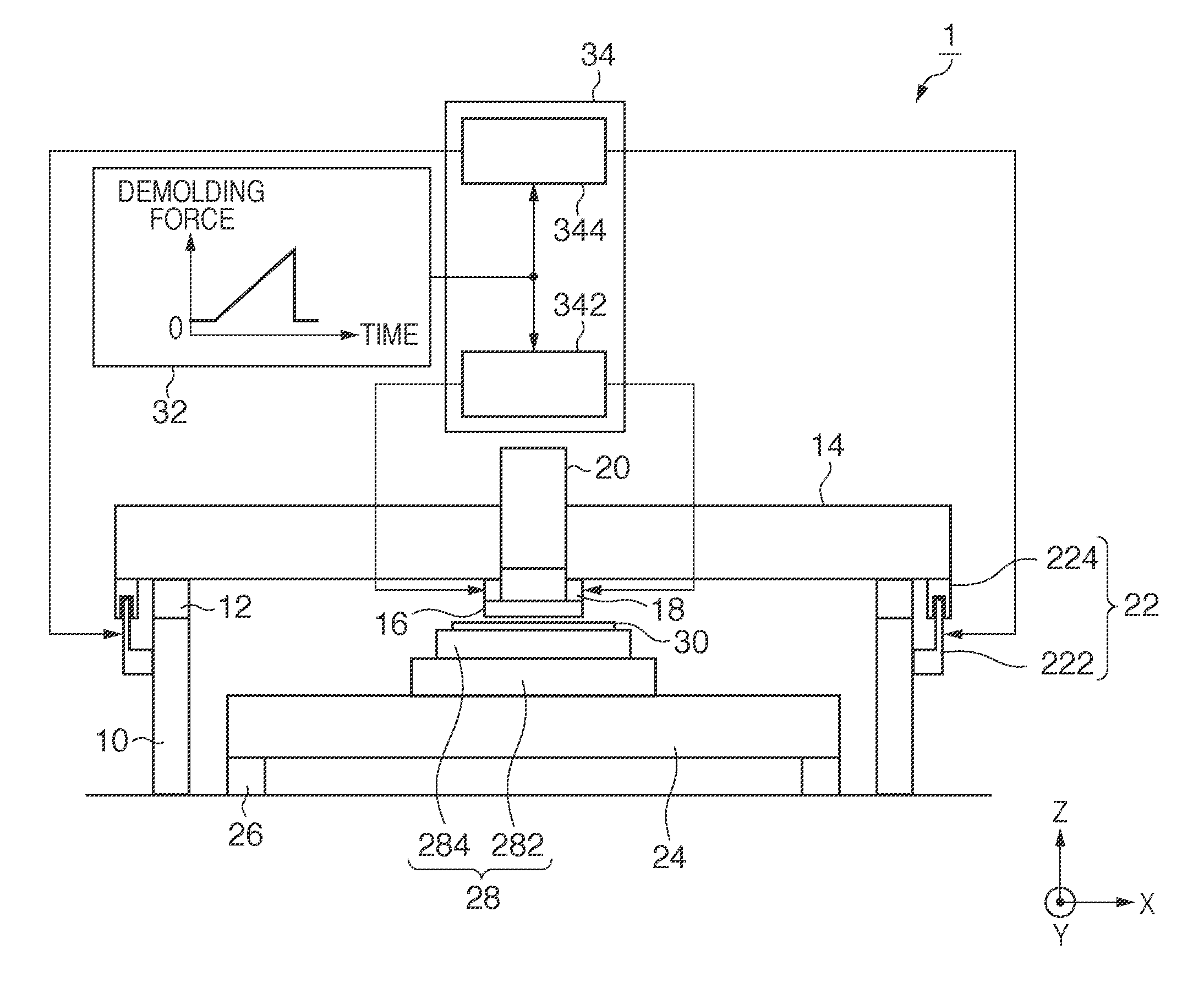
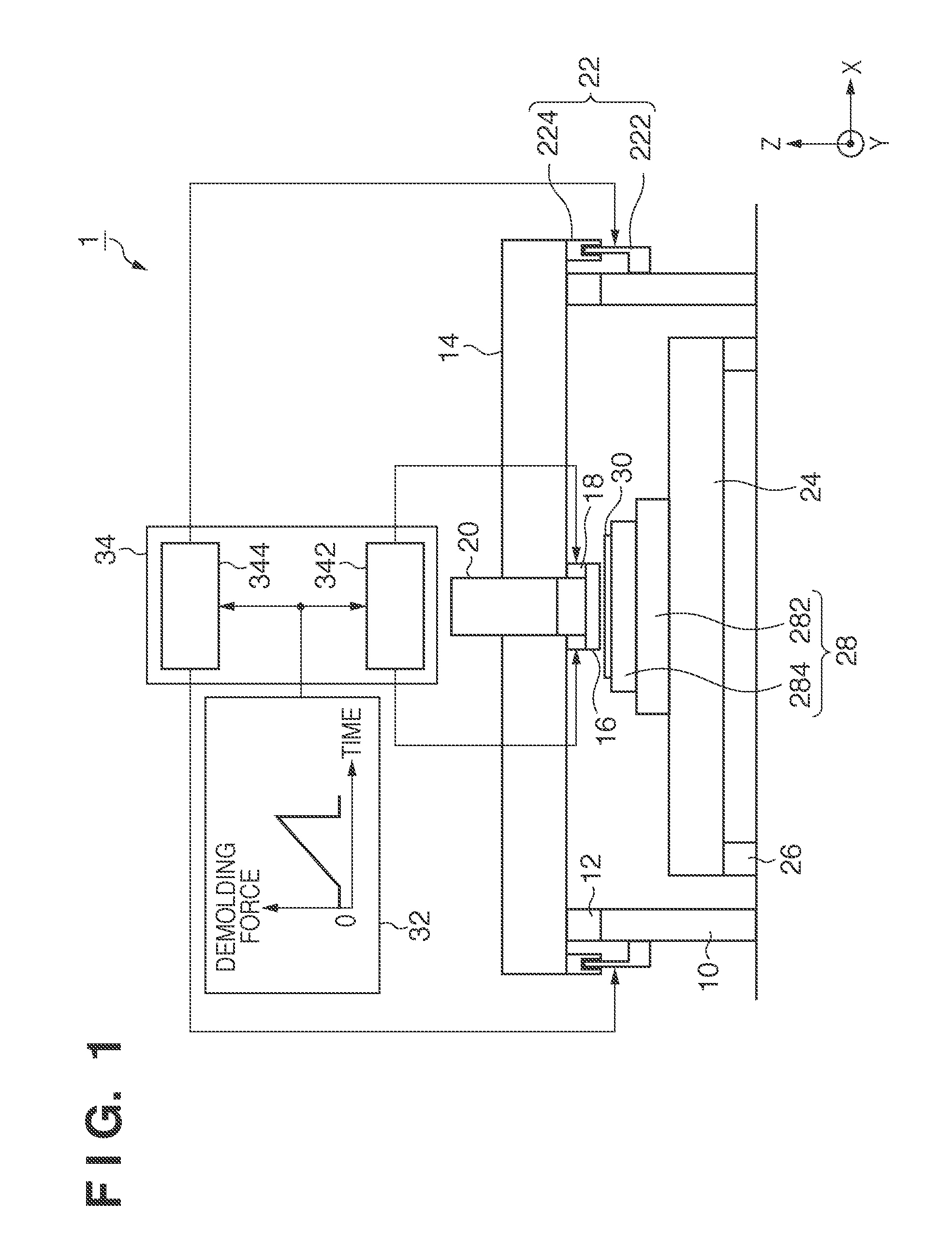
[0015]FIG. 1 is a diagram showing a configuration of an imprint apparatus 1 as an aspect of the present invention. The imprint apparatus 1 executes an imprint process, a curing process, and a demolding process (that is uses an imprint technique) to form a pattern on a substrate. The imprint process is a process of applying a resin on the substrate and pressing a mold (original plate) including a pattern against the substrate through the resin. The curing process is a process of curing the resin while the mold is being pressed against the substrate applied with the resin. The demolding process is a process of releasing the mold from the resin cured in the curing process.

[0016]As shown in FIG. 1, the imprint apparatus 1 includes a pillar 10, an anti-vibration mount 12, a structure 14, a mold 16, a mold driving unit 18, an illumination system 20, and a force providing unit 22. The imprint apparatus 1 further includes a stage base 24, an anti-vibration mount 26, a wafer stage 28, a prof...

second embodiment

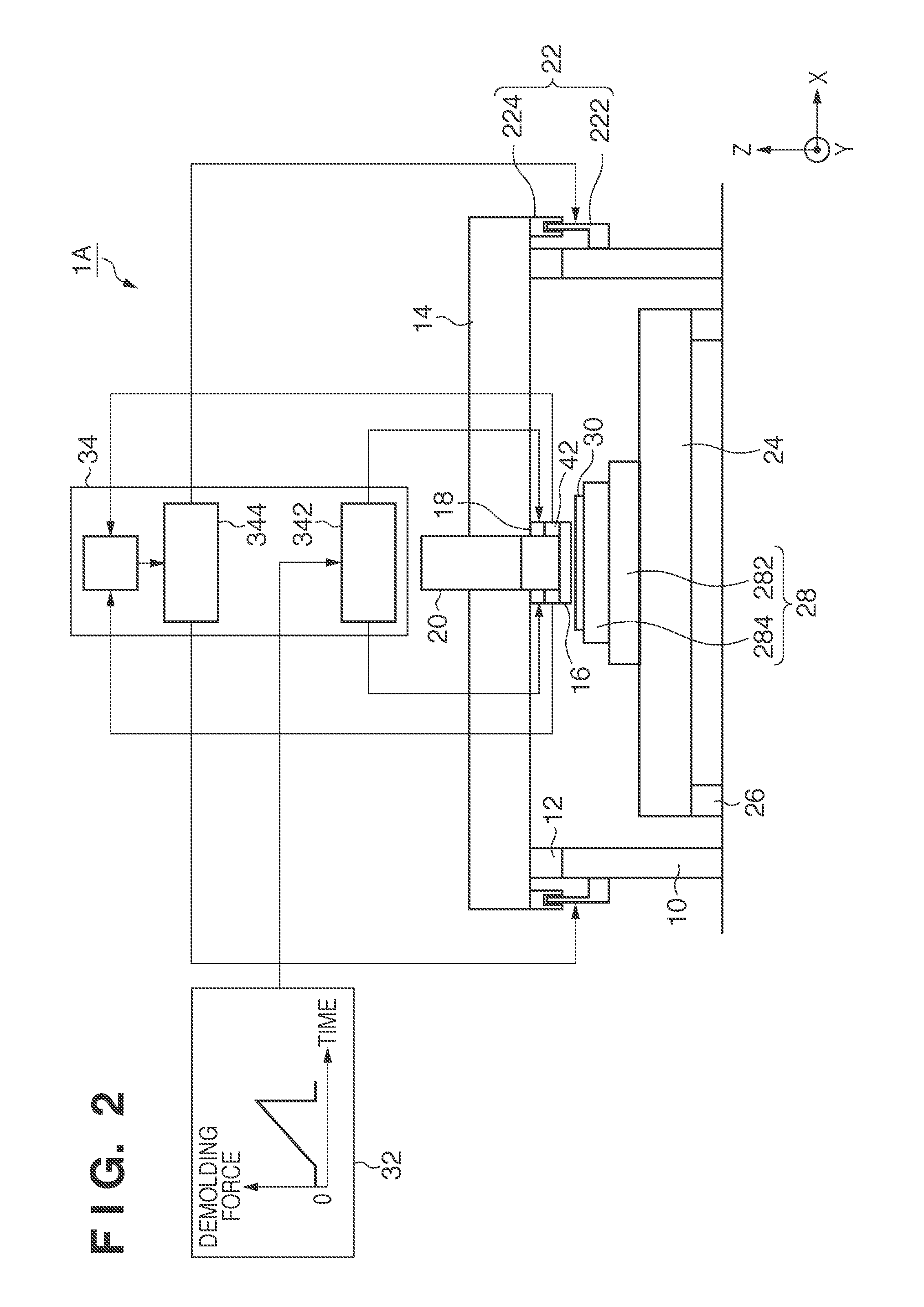
[0027]FIG. 2 is a diagram showing a configuration of an imprint apparatus 1A as an aspect of the present invention. In addition to the constituent elements of the imprint apparatus 1, the imprint apparatus 1A further includes a detection unit 42 that detects demolding force provided to the mold 16. In the imprint apparatus 1A, in addition to the first generation unit 342 and the second generation unit 344, the control unit 34 includes a profile conversion unit 346. The profile conversion unit 346 converts the detection result of the detection unit 42 to a profile equivalent to the profile generated by the profile generation unit 32 (that is profile indicating the demolding force detected by the detection unit 42 in chronological order). The point that the structure 14 is supported by the pillar 10 mechanically independently from the stage base 24 through the anti-vibration mount 12 and the point that force providing unit 22 generates force in the +Z direction between the pillar 10 a...


PUM

PropertyMeasurementUnit
demolding forceaaaaaaaaaa
forceaaaaaaaaaa
reactive forceaaaaaaaaaa

Abstract

The present invention provides an imprint apparatus including a mold and a stage that holds a substrate, the imprint apparatus executing a curing process of curing a resin while the mold and the resin applied to the substrate contact and a demolding process of releasing the mold from the resin cured in the curing process, the imprint apparatus including a structure that holds the mold, a pillar that supports the structure mechanically independently from the stage through an anti-vibration mount that reduces propagation of vibration, and a force providing unit that provides, to the structure, force in an opposite direction from a direction of force generated in the structure by providing demolding force to the mold during the demolding process.

Description

BACKGROUND OF THE INVENTION[0001]1. Field of the Invention[0002]The present invention relates to an imprint apparatus and a manufacturing method of commodities.[0003]2. Description of the Related Art[0004]In recent years, an imprint technique that allows formation of a fine pattern is drawing attention as a technique for manufacturing a semiconductor device. In the imprint technique, a resin is applied to a substrate, such as a silicon wafer and a glass plate, and the resin is cured while an original plate (mold) with a fine pattern is pressed against the substrate through the resin to form the fine pattern on the substrate. Examples of the curing method of the resin include a light curing method where ultraviolet light is directed to an ultraviolet curing resin and a heat curing method where heat is applied to a heat curing resin.[0005]An imprint apparatus using such an imprint technique is disclosed in Japanese Patent Laid-Open No. 2005-286062. A wafer stage for driving a wafer is...

Claims


Application Information

Patent Timeline
Patent Type & Authority Applications(United States)
IPC IPC(8): B29C59/02
CPCB82Y10/00B82Y40/00Y10S977/887H01L21/67092H01L21/67121G03F7/0002
Inventor KORENAGA, NOBUSHIGE
Owner CANON KK
Why Eureka
Try Eureka