

Shock absorbing steering apparatus
Patent Information
- Authority / Receiving Office
- US · United States
- Current Assignee / Owner
- JTEKT CORP
- Publication Date
- 2011-04-14
- Estimated Expiration
- Not applicable · inactive patent
Smart Images
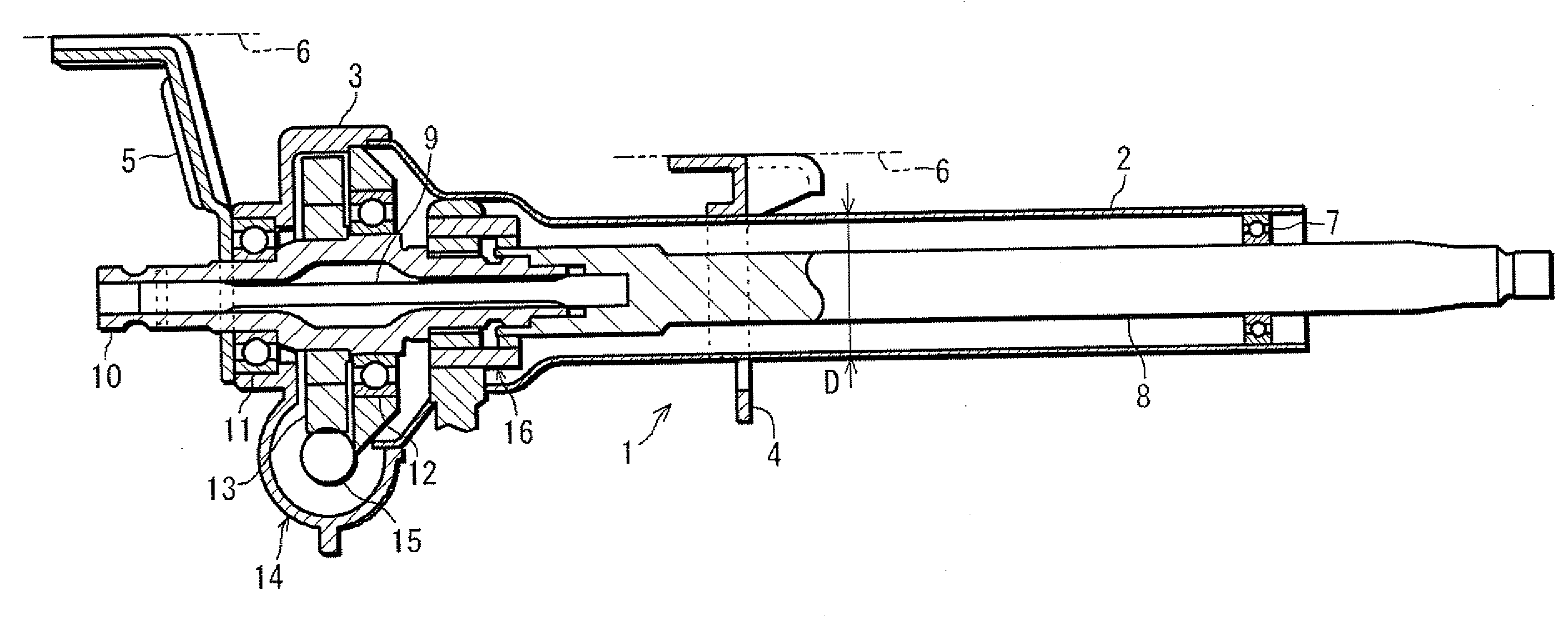
Figure 1 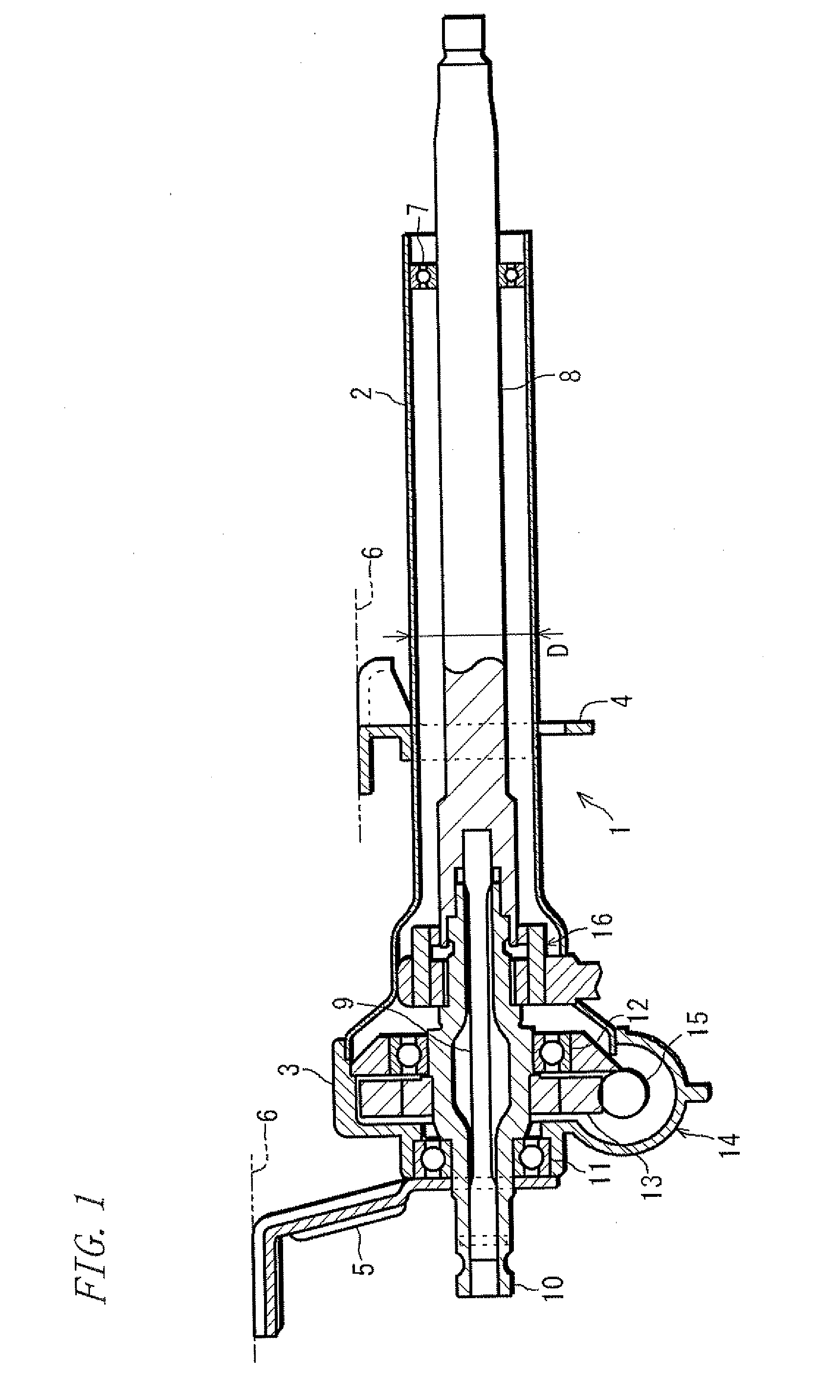
Figure 2 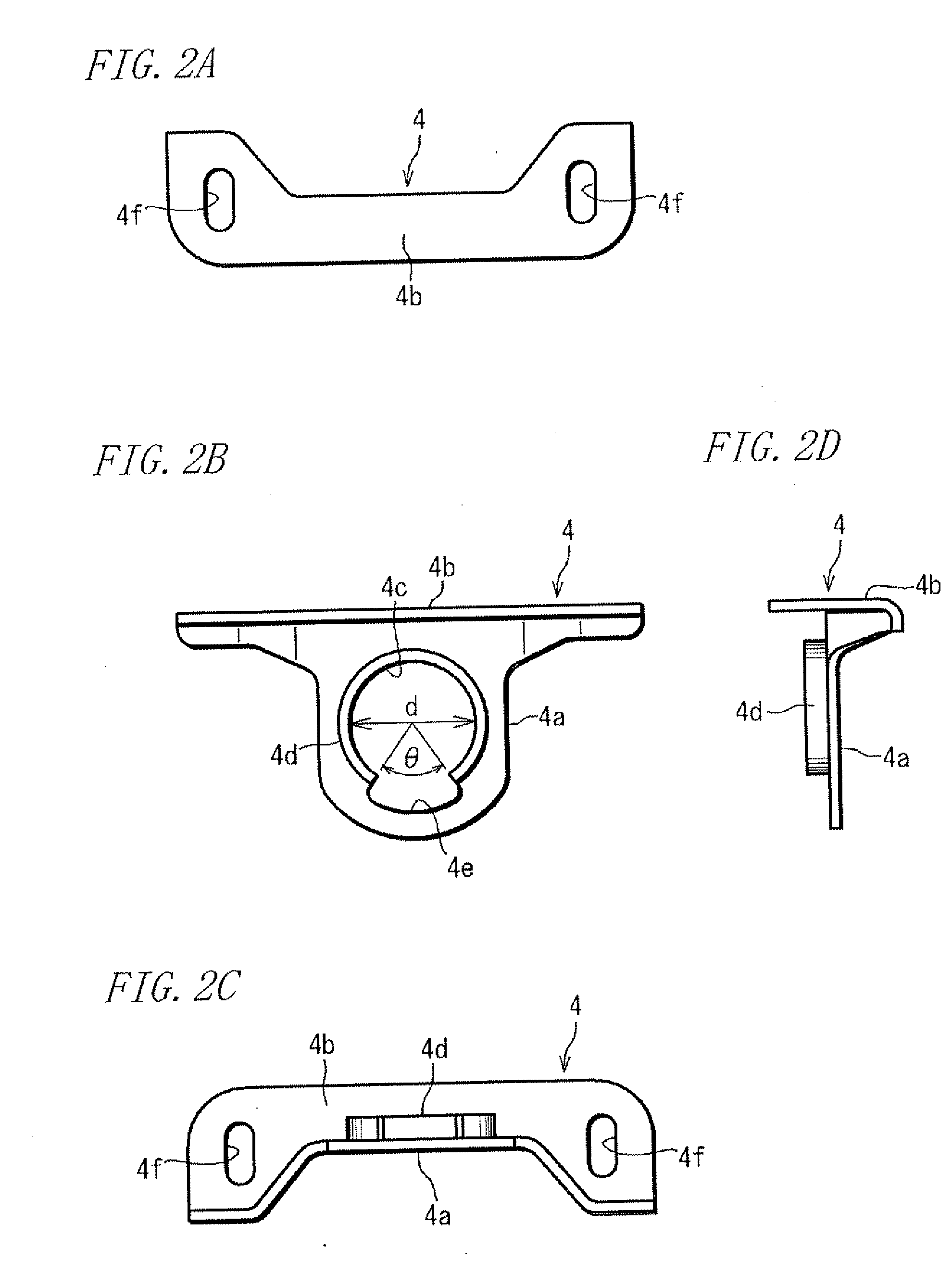
Figure 3
Abstract
Description
TECHNICAL FIELD
[0001] The present invention relates to a shock absorbing steering apparatus mounted in automotive vehicles.BACKGROUND ART
[0002] The shock absorbing steering apparatus is adapted to absorb impact energy of a secondary collision of a driver with a steering wheel when an automotive vehicle encounters a collision. More specifically, in a case where a column for supporting a steering shaft is mounted to a vehicle body by means of a bracket, for example, a breakaway capsule disengageable under a given load is interposed in between (see, for example Patent Document 1). The impact energy of the secondary collision is attenuated during the disengagement of this capsule.
[0003] There is also proposed a shock absorbing steering apparatus, for example, which includes an axially contractible column (see, for example Patent Document 2). Specifically, the column has a double tube structure wherein one cylinder tube overlaps with an outside surface of the other cylinder tube so that the...