Fully differential low-noise capacitor microphone circuit

a capacitor and capacitor technology, applied in the field of microphone electronics and circuits, can solve the problems of power supply noise, negative affecting signal-to-noise performance, and increasing power consumption

Inactive Publication Date: 2011-04-14
JAM IND USA
View PDF14 Cites 9 Cited by
  • Summary
  • Abstract
  • Description
  • Claims
  • Application Information

AI Technical Summary

Benefits of technology

[0010]According to one embodiment of this invention, a microphone circuit includes a capacitor capsule and first and second impedance converters connected differentially to the capacitor capsule. The microphone circuit can include first and second output buffer amplifiers connected differentially to the impedance converters. The microphone circuit can include a first output buffer amplifier connected to the first impedance converter and a second output buffer amplifier connected to the second impedance converter. The first impedance converter can include a first field effect transistor having a gate connected to a first terminal of the capacitor capsule, and the second impedance converter can include a second field effect transistor having a gate connected to a second terminal of the capacitor capsule. The first output buffer amplifier can include a first bipolar transistor having a base connected to a source of the first field effect transistor, and the second output buffer amplifier can include a second bipolar transistor including a base connected to a source of the second field effect transistor. The first impedance converter can include a first bootstrap capacitor that feeds the output of the first impedance converter back into the input of the first impedance converter, and the second impedance converter can include a second bootstrap capacitor that feeds the output of the second impedance converter back into the input of the second impedance converter. The first and second output buffer amplifiers can each form an emitter follower circuit. The first impedance converter can include a first current source, and the second impedance converter can include a second current source. The first current source can include a field effect transistor having a gate connected to the signal ground, a source connected to the signal ground through a resistor, and a drain connected to the first impedance converter. The second current source can include a field effect transistor having a gate connected to the signal ground, a source connected to the signal ground through a resistor, and a drain connected to the second impedance converter.

Problems solved by technology

Gate capacitance creates a voltage divider with the capsule capacitance and acts as a signal attenuator, which negatively affects signal-to-noise performance.
This noise can be reduced by decreasing the value of these resistors; however, reducing these resistors causes an increase in power consumption, which increases as the square of the cathodyne current.
The second major source is power supply noise.
Any noise present on the voltage source VDD will be algebraically added to the desired signal, thus limiting further signal-noise ratio improvements.

Method used


Image

  • Fully differential low-noise capacitor microphone circuit
  • Fully differential low-noise capacitor microphone circuit
  • Fully differential low-noise capacitor microphone circuit

Examples


Embodiment Construction

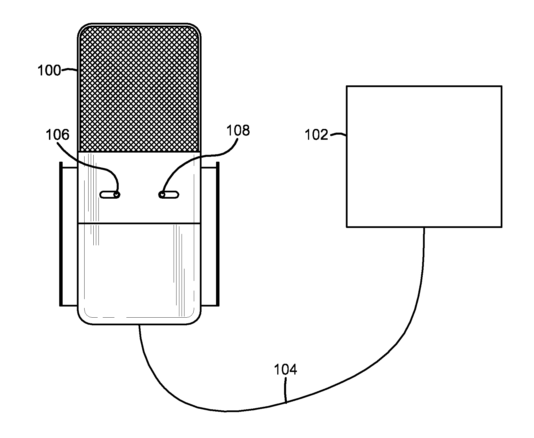
[0023]Referring now to the drawings wherein the showings are for purposes of illustrating embodiments of the invention only and not for purposes of limiting the same, and wherein like reference numerals are understood to refer to like components, FIG. 4 shows a condenser or capacitor microphone 100 including a microphone capsule or capacitor capsule, as is known in the art. Microphone capsules are also discussed in U.S. Non-Provisional patent application Ser. No. 12 / 783,396, titled VARIABLE PATTERN HANGING MICROPHONE SYSTEM WITH REMOTE POLAR CONTROL, filed May 19, 2010, which is herein incorporated by reference in its entirety. The microphone 100 can be connected to a microphone preamplifier or mixing console 102 with a microphone cable 104. The microphone 100 can include an attenuation switch 106, a hi-pass switch 108, and a microphone circuit 110. In some embodiments, the attenuation switch 106 activates a 10 dB pad and the hi-pass switch 108 activates an 80 Hz hi-pass filter. Acc...


PUM

PropertyMeasurementUnit
impedanceaaaaaaaaaa
voltageaaaaaaaaaa
voltageaaaaaaaaaa

Abstract

A microphone circuit includes a capacitor capsule and first and second impedance converters connected differentially to the capacitor capsule. The microphone circuit includes first and second output buffer amplifiers connected differentially to the first and second impedance converters.

Description

CROSS-REFERENCE TO RELATED APPLICATIONS[0001]This application claims the benefit of U.S. Provisional Application No. 61 / 250,905, titled FULLY DIFFERENTIAL LOW-NOISE CAPACITOR MICROPHONE CIRCUIT, filed Oct. 13, 2009, which is herein incorporated by reference.I. BACKGROUND[0002]A. Field of Invention[0003]The present invention relates generally to microphones and more specifically to microphone electronics and circuits.[0004]B. Description of the Related Art[0005]Typical capacitor microphones include a microphone circuit 10 having a capacitor microphone capsule 12, an impedance converter 14, a phase splitter 16, and two output buffer amplifiers 18, 20, as shown in FIG. 1 of the prior art. Two output buffer amplifiers 18, 20 are generally needed because the output 22 of professional microphones is usually differential and impedance balanced. These output signals are subtracted in the microphone preamplifier or mixing console to minimize the effects of cable capacitance as well as to can...

Claims


Application Information

Patent Timeline
Patent Type & Authority Applications(United States)
IPC IPC(8): H04R11/04H04R31/00
CPCH04R19/04Y10T29/49005
Inventor EJAZ, MUHAMMADSTATHAM, KELLY
Owner JAM IND USA
Why Eureka
Try Eureka