Plasma device with low thermal noise

a technology of thermal noise and plasma, applied in the direction of plasma technique, coating, electric discharge lamps, etc., can solve the problem of low thermal noise level, achieve the effect of reducing thermal noise, temperature, resistance, and/or collision frequency, and acceptable noise and snr levels

Active Publication Date: 2011-12-13
ANDERSON THEODORE R
View PDF11 Cites 9 Cited by
  • Summary
  • Abstract
  • Description
  • Claims
  • Application Information

AI Technical Summary

Benefits of technology

[0015]A plasma device having reduced thermal noise is disclosed. In particular, the plasma device is operated in such a manner that the temperature, resistance, and / or collision frequency are reduced and / or the operating frequency is increased to produce an acceptable level of noise and SNR. These parameters are changed indirectly or directly by taking advantage of the Ramsauer-Townsend effect, by operating in the afterglow state, by reducing the plasma electron temperature, and / or by otherwise directly changing the parameters. In this way, the plasma device is operated without excessive thermal noise and with a high SNR in low level signal conditions as contrasted to comparable metal devices.
[0018]In one embodiment, the physical dimensions and configuration of a plasma device are selected based on the operating frequency of the plasma device. The characteristics of the plasma are controlled to produce a plasma device having a low level of thermal noise. In one embodiment, the electron collision frequency is minimized relative to the operating frequency to reduce the thermal noise. In one such embodiment, a Ramsauer gas is used in the plasma device to reduce the electron-gas atom collision frequency.

Problems solved by technology

In one embodiment, the plasma device is operated at a selected frequency with a selected gas pressure and temperature that results in a lower thermal noise level than that of a metal device operated at the same selected frequency and with a similar design.

Method used


Image

  • Plasma device with low thermal noise
  • Plasma device with low thermal noise
  • Plasma device with low thermal noise

Examples


Embodiment Construction

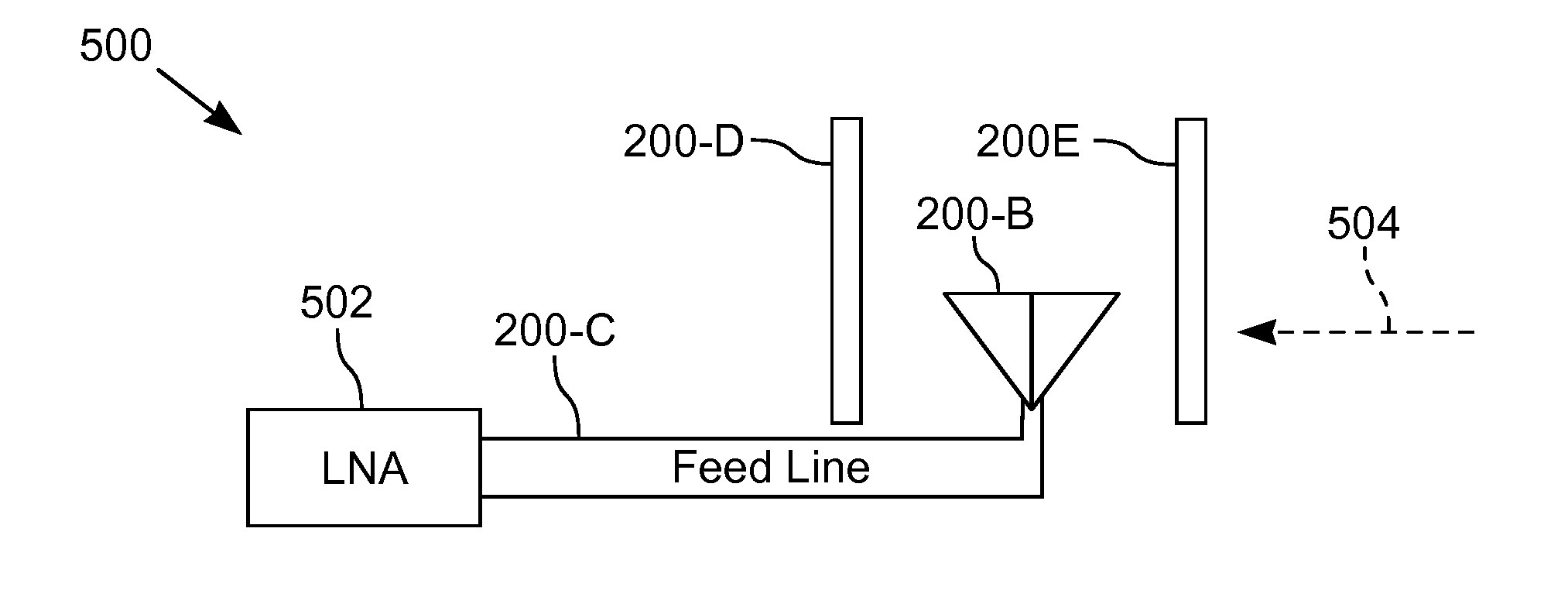
[0029]A plasma device with low thermal noise is disclosed. Although specific examples of plasma devices are described herein, for example, a plasma antenna 200-A, a person skilled in the art will recognize that the plasma device not limited to the provided examples. As used herein, a plasma device includes devices that include a plasma that is responsive to electromagnetic radiation and / or electrical signals. Examples of a plasma device include a plasma antenna, a plasma reflector, a plasma screen, a plasma shield, a plasma window, a plasma switch, a plasma waveguide, plasma circuit conductors such as a coaxial cable, a plasma radome, and plasma frequency selective surfaces.

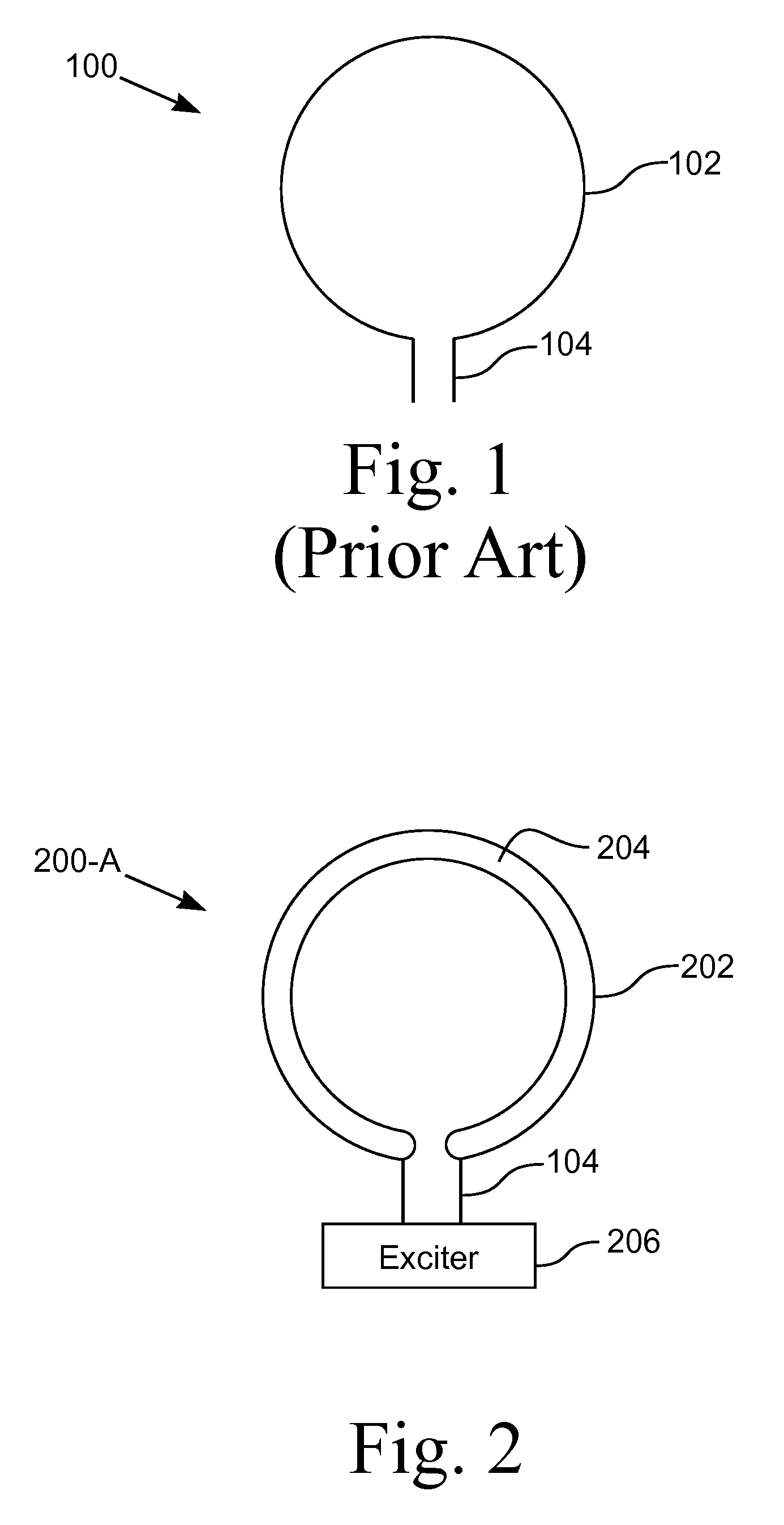
[0030]FIG. 2 illustrates one embodiment of a plasma device, namely, a plasma antenna 200-A. The illustrated plasma antenna 200-A is a loop antenna. In various embodiments, the plasma antenna 200-A has various configurations, for example, dipole, folded dipole, beam, and loop. The plasma antenna 200-A includes a v...


PUM

PropertyMeasurementUnit
operating frequencyaaaaaaaaaa
thermal noise levelaaaaaaaaaa
electrically non-conductiveaaaaaaaaaa

Abstract

A plasma device having low thermal noise, which results in a high signal-to-noise ratio (SNR) of the plasma device. The plasma device includes devices with a plasma that is responsive to electromagnetic radiation and / or electrical signals. In various configurations, the plasma device has a plasma in which the temperature, resistance, pressure, and / or collision frequency are at a level sufficiently low to produce an acceptable level of noise. In another configuration, the operating frequency of the plasma device is at a level sufficiently high to produce an acceptable level of noise. Decreasing the noise level results in increasing the signal-to-noise ratio and increasing the data rate. The plasma temperature is reduced by operating the plasma device in the afterglow state. The plasma electron temperature is reduced by confining high energy electrons in a potential well and by using an electron emitting filament.

Description

CROSS-REFERENCE TO RELATED APPLICATIONS[0001]This application claims the benefit of U.S. Provisional Application No. 60 / 990,830, filed Nov. 28, 2007.STATEMENT REGARDING FEDERALLY SPONSORED RESEARCH OR DEVELOPMENT[0002]Not ApplicableBACKGROUND OF THE INVENTION[0003]1. Field of Invention[0004]This invention pertains to a plasma device with low thermal noise. More particularly, this invention pertains to a plasma device in which the device parameters are selected to provide an optimum noise level and signal-to-noise ratio.[0005]2. Description of the Related Art[0006]The signal-to-noise ratio (SNR) is the power ratio between a signal and noise. A high SNR is desirable because noise corrupts the signal, potentially reducing the bandwidth of the signal. Sources of noise include both external and internal sources. External sources include man-made noise, such as radio-frequency interference (RFI), and naturally generated noise, such as lightning and background or black body radiation. Inte...

Claims


Application Information

Patent Timeline
Patent Type & Authority Patents(United States)
IPC IPC(8): H01Q1/26H01J7/24
CPCH05H1/46
Inventor ANDERSON, THEODORE R.ALEXEFF, IGOR
Owner ANDERSON THEODORE R
Why Eureka
Try Eureka