Single mode optical fiber with depressed trench

a single-mode optical fiber and trench technology, applied in the field of line fibers, can solve the problems of increasing transmission losses, difficult to obtain and higher cost of producing fibers with doped cladding than fibers with pure silica cladding, so as to limit the leakage loss in lp01 propagation mode, the effect of reducing the radius of doped cladding

Active Publication Date: 2011-04-14
DRAKA COMTEQ BV
View PDF14 Cites 44 Cited by
  • Summary
  • Abstract
  • Description
  • Claims
  • Application Information

AI Technical Summary

Benefits of technology

[0015]To this end, it is proposed to reduce the doped cladding radius by adding a depressed trench in the inner cladding. The depressed trench has characteristics making it possible to limit leakage losses in LP01 propagation mode which are drastically increased when an outer optical cladding having a refractive index close to that of silica is brought close to the central core. The trench structure and position are chosen so as to obtain the best compromise.
[0017]In essence the aim of the present invention is to add a depressed trench is refractive index profiles having a low refractive index of the central core—and consequently having leakage losses) in order to be able to move the outer optical cladding closer to the central core—in order to reduce manufacturing costs and for reasons of compatibility with large volumes of manufacturing—but while keeping a low cable cut-off wavelength.

Problems solved by technology

For instance, in a radioactive environment, germanium will combine with hydrogen present in the atmosphere and lead to significant fiber defects thereby increasing transmission losses.
Nevertheless, it is difficult to obtain fibers having a doped cladding.
The cost of producing a fiber with a doped cladding is higher than that for a fiber having a cladding in pure silica.
Nevertheless, this method is limited as the outer optical cladding, which has a refractive index close to that of the core, needs to be placed sufficiently far away from the latter.
In effect, the proximity of the silica cladding brings about an increase in fundamental propagation mode LP01 leakage losses.
But this document does not give details of the characteristics of the depressed inner cladding and of the depressed trench making it possible to obtain low leakage losses for the fundamental mode and a low cut-off wavelength.
The characteristics of the fiber do consequently not allow it to provide minimized doped cladding radius while preserving low fundamental mode leakage losses and a low cable cut-off wavelength (less than 1550 nm).
The characteristics of this fiber do not consequently allow it to provide a minimized doped cladding radius while preserving low fundamental mode leakage losses.
Further, the radius of the trench located at the periphery of the inner cladding is fairly small (<28 μm), which does not make it possible to obtain low fundamental mode leakage losses.

Method used


Image

  • Single mode optical fiber with depressed trench
  • Single mode optical fiber with depressed trench

Examples


first embodiment

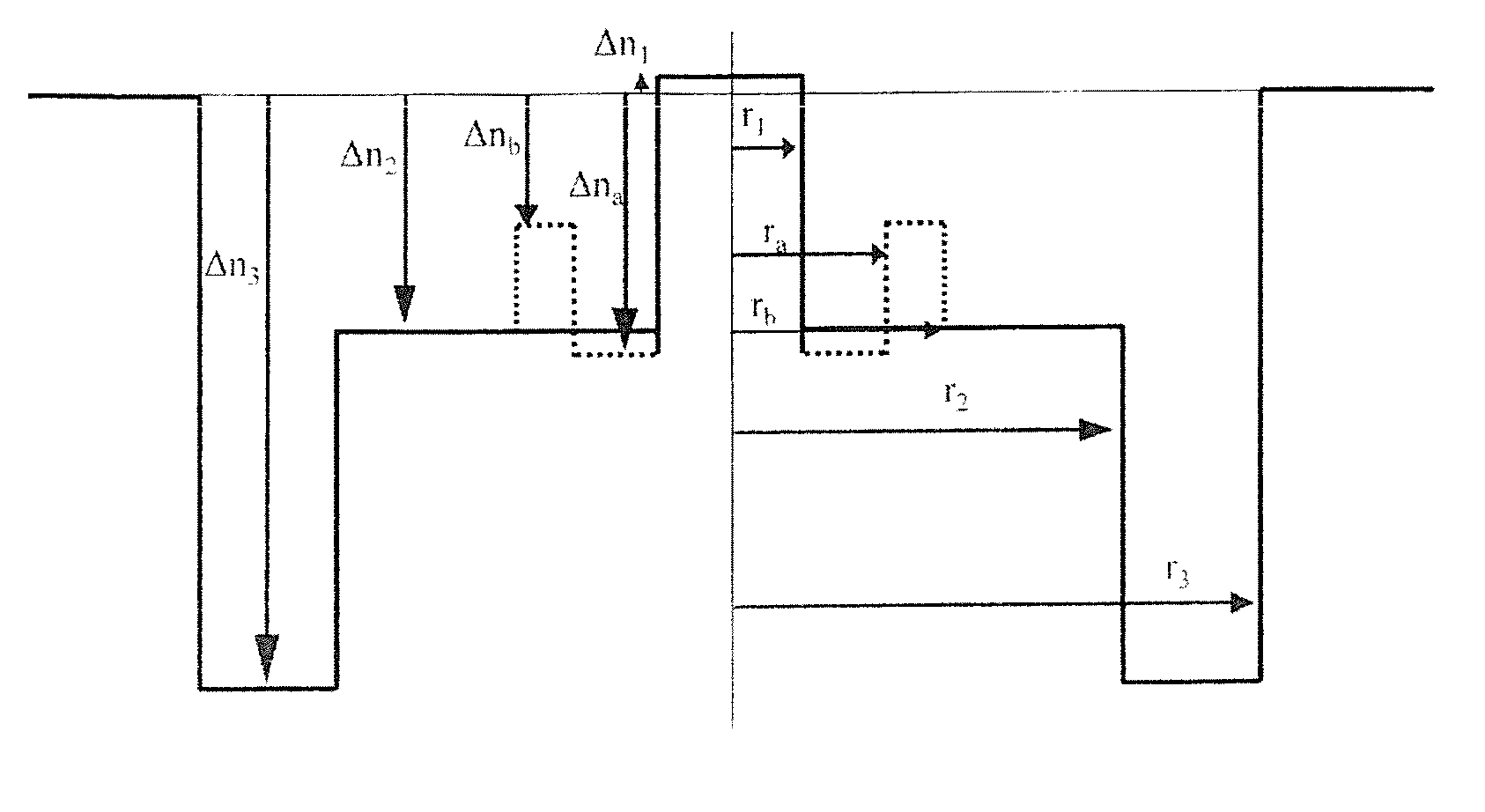
[0050]According to the present invention illustrated in FIG. 1, the second portion of the depressed inner cladding constitutes the outer periphery of the depressed inner cladding. In other words, the second portion is directly surrounded by the outer optical cladding. In FIG. 1, the outer radius of the depressed inner cladding comprised between 28 and 40 μm, or even between 28 and 38 μm, or yet even between 28 and 36 μm, consequently corresponds to the radius r3 of the second portion of the depressed inner cladding. In this embodiment, the radius r2 of the first portion of the depressed inner cladding is such that the ratio r2 / r1 is greater than 6. This value ensures that the cable cut-off wavelength λcc is less than 1530 nm without this bringing about an increase in fundamental mode leakage losses.

second embodiment

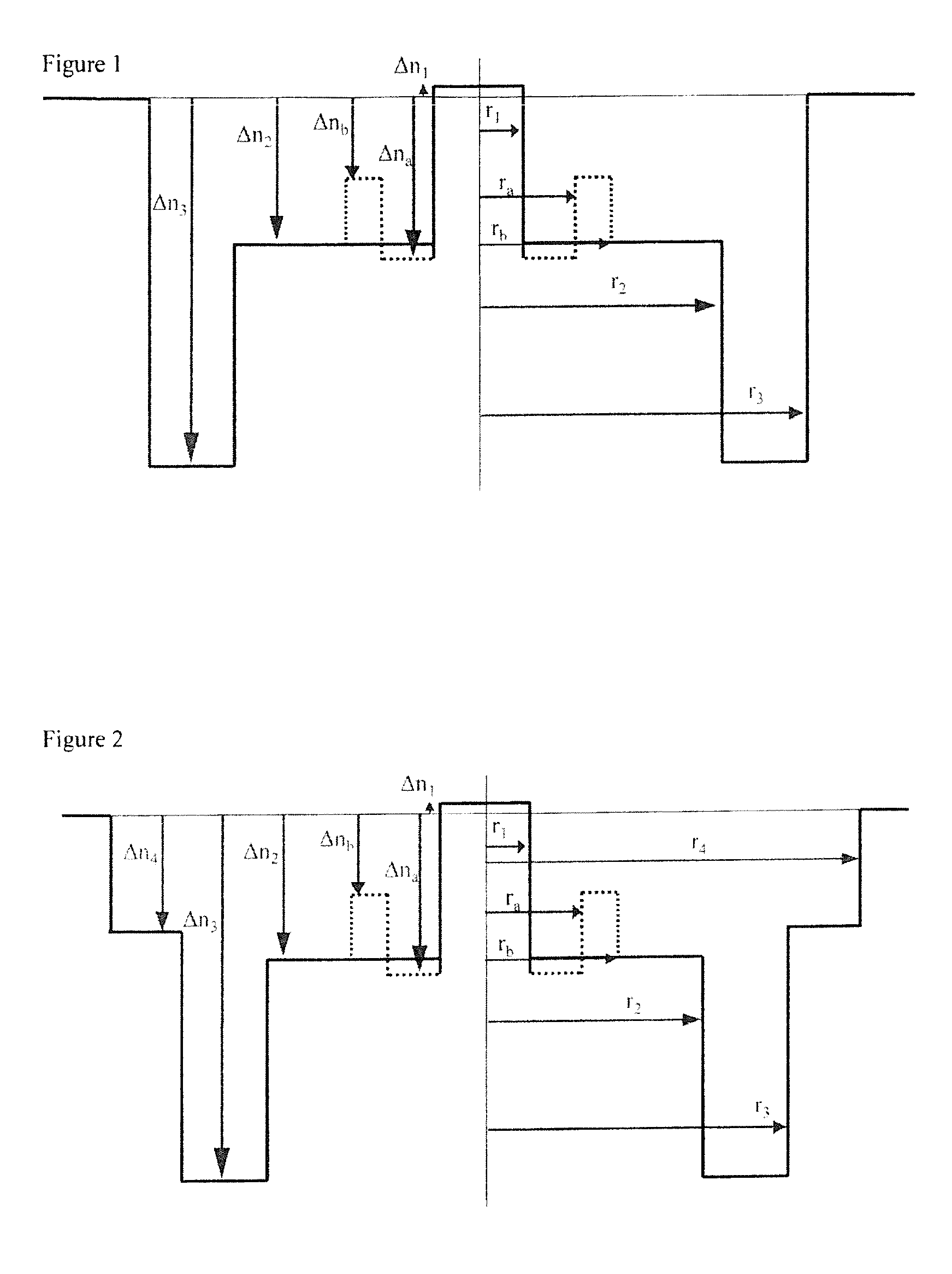
[0051]In the present invention illustrated in FIG. 2, the second portion of the depressed inner cladding does not constitute the outer periphery of the depressed inner cladding. This depressed inner cladding further comprises a third portion that is supplementary or additional and that is located between the second portion of the depressed inner cladding and the outer optical cladding. In this embodiment, this third portion constitutes the outer periphery of the depressed inner cladding. This third portion of the depressed inner cladding has a radius r4 and a refractive index difference Δn4 with the outer optical cladding that is greater than the refractive index difference Δn3 of the second portion of the depressed inner cladding. The refractive index of the third portion is greater (i.e. less negative) than that of the second portion of the depressed inner cladding. In FIG. 2, the outer radius of the depressed inner cladding comprised between 28 and 40 μm, or yet even between 28 a...


PUM

PropertyMeasurementUnit
outer radiusaaaaaaaaaa
cut-off wavelengthaaaaaaaaaa

Abstract

An optical fiber having a core and an outer cladding, the core including from its center outward a central core having a radius and a refractive index difference with respect to the outer cladding, and a depressed inner cladding. The depressed inner cladding includes at least a first portion having a radius and a refractive index difference with respect to the outer cladding, the first portion preferably being adjacent to the central core, and a second portion adjacent to the first portion constituting a depressed trench having a radius, and a refractive index difference with respect to the outer cladding. The first portion of the inner cladding has a refractive index below the refractive index of the outer cladding, and the depressed trench has a refractive index that is lower than the refractive index of the first portion of the depressed inner cladding. The outer radius of the depressed inner cladding of the optical fiber is between 28 μm and 40 μm, the LP01 mode leakage losses at a wavelength of 1550 nm are less than 0.01 dB / km and the cable cut-off wavelength is less than 1530 nm.

Description

TECHNICAL FIELD AND BACKGROUND OF THE INVENTION[0001]The present invention relates to the field of transmission by optical fiber and more specifically to a line fiber for long-distance applications.[0002]An optical fiber conventionally consists of a central core having the function transmitting and possibly amplifying an optical signal, and an outer optical cladding, having the purpose of confining the optical signal within the central core. For this purpose, the refractive indices of the central core nc and the outer optical cladding ng are such that nc>ng.[0003]For optical fibers, the index profile is generally qualified as a function of the shape of a graph showing the relation between fiber radius and refractive index. Conventionally, the x-axis gives the distance r from the centre of the fiber while the y-axis shows the difference between the refractive index and the refractive index of the fiber cladding. Thus speaking of a “step”, “trapezium” or “triangle” index profile fo...

Claims


Application Information

Patent Timeline
Patent Type & Authority Applications(United States)
IPC IPC(8): G02B6/02
CPCG02B6/0365G02B6/03688G02B6/03683C03B2203/22C03B2201/12C03B2203/23C03B2201/31
Inventor BIGOT-ASTRUC, MARIANNESILLARD, PIERREDE MONTMORILLON, LOUIS-ANNEMOLIN, DENISRICHARD, SIMON
Owner DRAKA COMTEQ BV
Why Eureka
Try Eureka