[0008]One object of the present invention is to provide a mechanism for attenuating torque pulsations between an engine and a rotorcraft rotor driven in rotation by the engine, the mechanism having a size and weight that make it suitable for use in rotorcraft. It is particularly desirable for such a mechanism to be simple in structure, light in weight, and compact in order to make it acceptable for use in an aircraft, in particular a rotorcraft, that is to be lifted by means of at least one rotor and caused to move through the air. Nevertheless, such a mechanism must be robust so as to be long-lasting in
spite of the high levels of torque transmitted between the engine and the rotor. Such a mechanism must also be capable of being easily mounted in the
transmission system between the engine and the rotor it drives, and it must make it easy to perform any maintenance operations that might be required, whether on the mechanism itself or on other members making up the transmission
system.
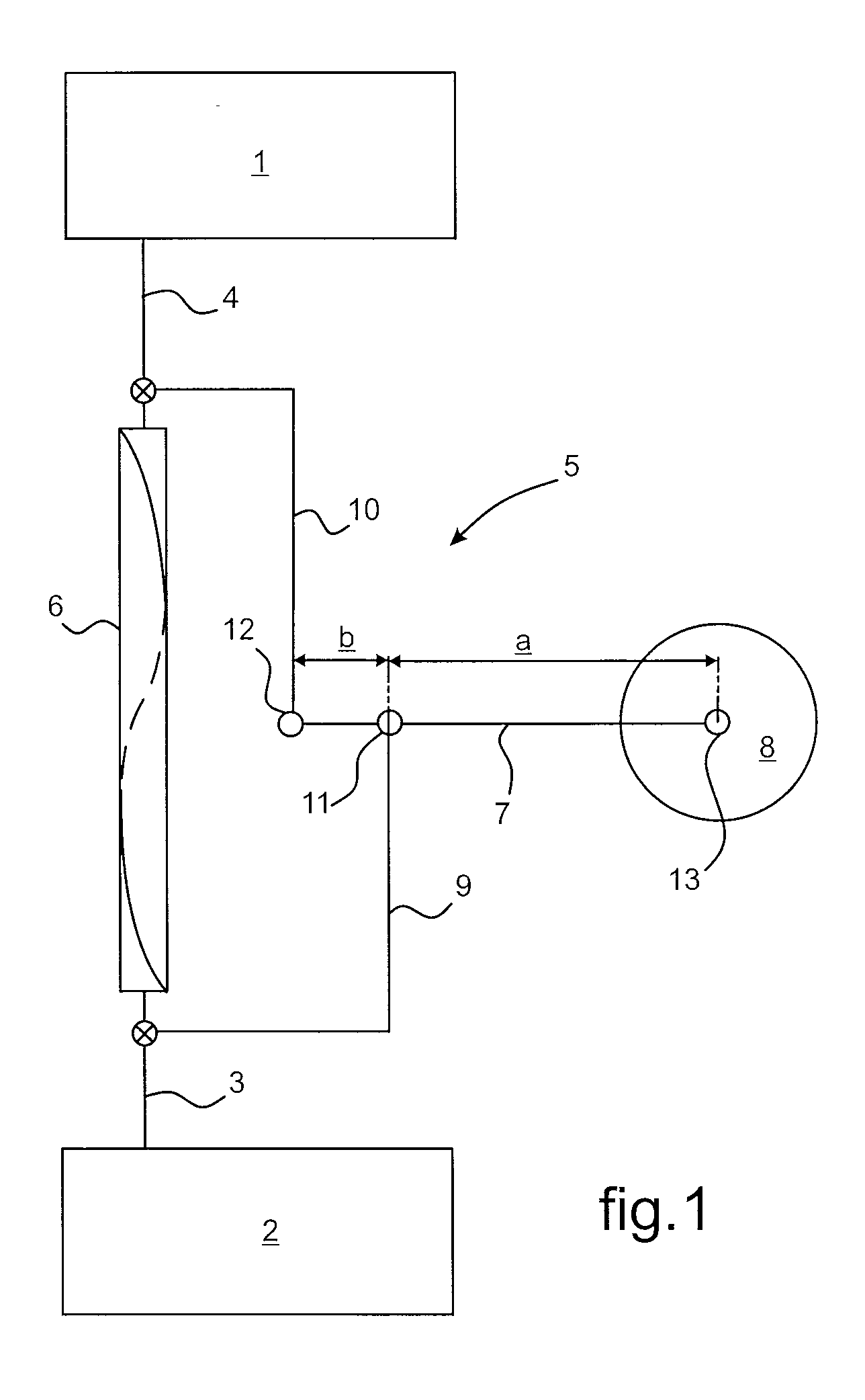
[0016]Under the effect of
centrifugal force and the force of
inertia as induced by the drive shaft being set into rotation, the
mass serves to give rise to phase shifts between the inlet shaft and the outlet shaft as a function of the torque pulsations induced by the resistance offered by the driven shaft against being driven in rotation by the drive shaft. These phase shifts are absorbed by the torsion shaft. The force multiplication effect produced by the lever
system serves to limit the
mass that needs to be used to achieve absorption of given induced torque pulsations. In
spite of the small mass used for causing the torsion shaft to twist, it nevertheless compensates the force of the torsion shaft in phase opposition by making use of the lever effect provided by the lever system. As a function of the
centrifugal force and the force of
inertia induced by setting the drive shaft into rotation, the mass of effect that is amplified by the lever system spontaneously causes torque pulsations to be absorbed. More particularly, the force transmissions induced by the torque pulsations at a given frequency are absorbed while not affecting the transmission of torque between the drive shaft and the driven shaft. Using the lever system makes it possible to reduce the mass for the torsion shaft acting to absorb the torque pulsations, such that there is no need for the mass and the extent of said torsion shaft to be unacceptable for an application in the field of rotorcraft. More particularly, the lever system serves to increase the stiffness of the torsion shaft and consequently to
restrict its extension, with the
advantage of making it suitable for use in the field of rotorcraft. The radial extent of the lever arm and its pivoting movement about the common axis of the torsion shaft, the inlet shaft, and the outlet shaft, give rise to the mass rocking tangentially relative to said common axis, while avoiding giving rise to unbalance that would affect the equilibrium of the forces involved when driving the rotor.
[0023]In an improved embodiment, the inlet shaft or the outlet shaft that is hinged to the lever arm between its said ends is in hinged connection with said lever arm via a link. This embodiment presents the
advantage of avoiding a statically undetermined configuration for the mechanism. The pivoting of the mass and the hinged junction to the corresponding shaft via the link acts under the effect of
centrifugal force to obtain greater stiffness for this pivoting and consequently makes it possible to further reduce the overall size of the torsion shaft, in particular in terms of
diameter, for given stiffness.
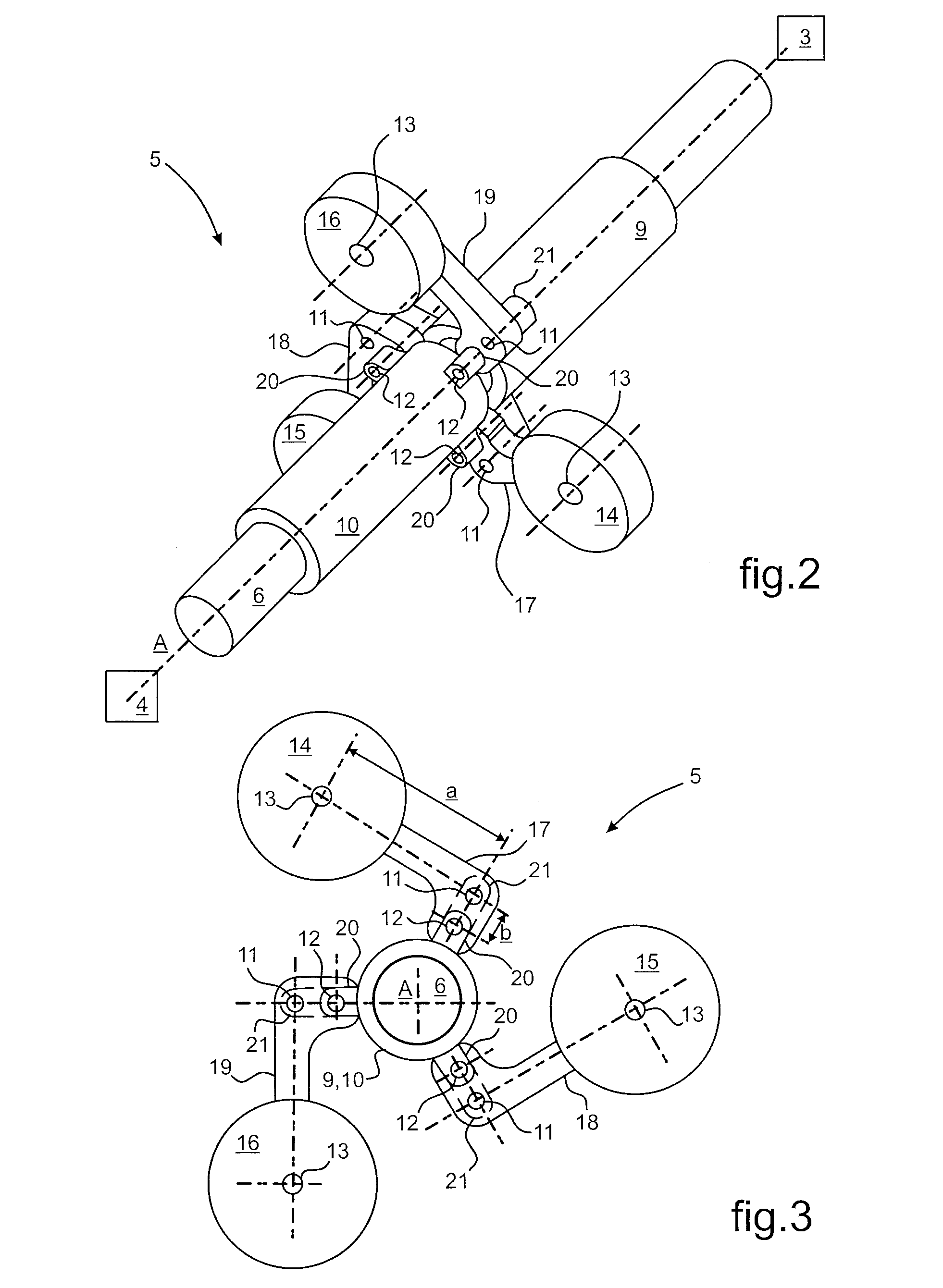
[0035]Between its ends, the lever arm may form an angle
lying in the range 90° to 180°. Ideally, in order to avoid making the mechanism excessively large in a radial direction, the lever arm forms a 90° bend between its ends, the corresponding inlet and / or outlet shafts being hinged in the zone of the bend. Taken together, the arrangement of the lever arm with a 90° angle between its ends and a said lever ratio of less than 10 makes it possible to
restrict the overall radial size of the mechanism as well as possible.
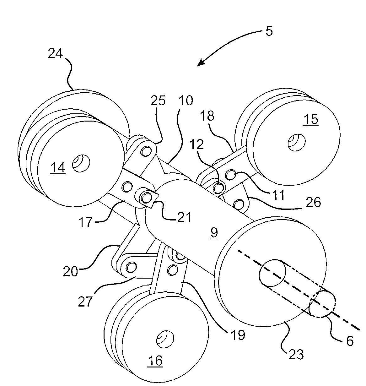
[0036]The mass is advantageously made up of a plurality of flyweights that are radially uniformly distributed, i.e. circumferentially uniformly distributed about the common coaxial axis along which the inlet, outlet, and torsion shafts extend. These flyweights are individually carried by respective individual lever arms to which the inlet and outlet shafts are hinged. The effect of centrifugal force and of the force of
inertia is radially distributed over the inlet and outlet shafts thus making it possible to balance the forces induced on the torsion shaft in order to damp torque pulsations, thereby also serving to avoid unbalance.
[0037]In an elementary embodiment providing both an effect of attenuating torque pulsations and balanced transmission of forces to the torsion shaft, and that is satisfactory for producing a mechanism of small radial size, the flyweights and the individual lever arms are preferably three in number, being radially uniformly distributed at 120° intervals about the common coaxial axis along which the inlet, outlet, and torsion shafts extend.
