
Mixing unit, mixing device, agitation impeller, pump mixer, mixing system and reaction device

a technology of mixing unit and pump mixer, which is applied in the direction of rotary stirring mixer, transporting and packaging, chemical/physical/physicochemical processes, etc., can solve the problems of disadvantageously needing to use a large amount of power, limited mixing effect, and increased pressure drop in the entire device, so as to achieve effective mixing of fluid, reliably mixing fluid, and enhanced mixing

Active Publication Date: 2011-04-14
ISEL CO LTD
View PDF19 Cites 14 Cited by
  • Summary
  • Abstract
  • Description
  • Claims
  • Application Information

AI Technical Summary

Benefits of technology

[0058]As described above, according to the mixing unit and the mixing device of the present invention, the fluid flows through the first through holes communicating with each other, and thus the mixing effects are enhanced.
[0059]Moreover, according the agitation impeller of the present invention, the fluid flows through the first through holes communicating with each other, and thus it is possible to effectively mix the fluid.
[0060]Furthermore, according to the pump mixer of the present invention, since the fluid sacked through the suction port of the pump mixer is passed through the first through holes communicating with each other within the stacked member of the mixing unit and is discharged through the discharge port, it is possible to-continuously mix the fluid. It is also possible to discharge the fluid sucked through the suction port of the pump mixer through the discharge port at high pressure. Moreover, according to the mixing system of the present invention, since the fluid can be repeatedly passed through the pump mixer, it is possible to reliably mix the fluid.
[0061]Furthermore, according to the reaction device of the present invention, since the fluid is passed through the first through holes communicating with the inside of the stacked member of the mixing unit, the effect of mixing the fluid is enhanced, and thus it is possible to increase a conversion in the downstream catalyst layer.

Problems solved by technology

However, since, in the fluid mixing device, the area of a fluid flow passage is composed of the areas of only parts through which the compartments of the two discs, the large and small discs, communicate with each other, the mixing effects are limited.
As the flow rate of the fluid is increased, the pressure drop produced in the entire device is increased; thus, it is disadvantageously necessary to use a large amount of power.
Since the residues of the fluid and foreign matter are adhered to dead spaces in the compartments, a washing operation for maintenance is time-consuming.
However, in the agitation blade described above, the fluid is mixed only in the areas around the partially agitating units fitted to the supporting member, and the efficiency of mixing is therefore limited.
However, when mixing is performed by the mixing device, since the cooling gas flow is locally injected into the high-temperature gas flow through the pierced supply portion placed in the annular space, the gases are insufficiently mixed around the pierced supply portion.
Therefore, a deflector is provided to improve the mixing effects but the mixing effects are limited.
Moreover, when an operation is performed with a small amount of gas flow supplied to the reactor and a light load thus imposed on the reactor, since the speed of the cooling gas flow supplied through the holes in the pierced supply portion is reduced, the effects of mixture with the high-temperature gas flow are disadvantageously further reduced.
Furthermore, the pierced supply portion for supplying the cooling gas flow is placed in the annular space, and it therefore becomes difficult to produce the annular space as the size of the reactor is increased.

Method used


Image

  • Mixing unit, mixing device, agitation impeller, pump mixer, mixing system and reaction device
  • Mixing unit, mixing device, agitation impeller, pump mixer, mixing system and reaction device
  • Mixing unit, mixing device, agitation impeller, pump mixer, mixing system and reaction device

Examples


first embodiment

of a Mixing Unit

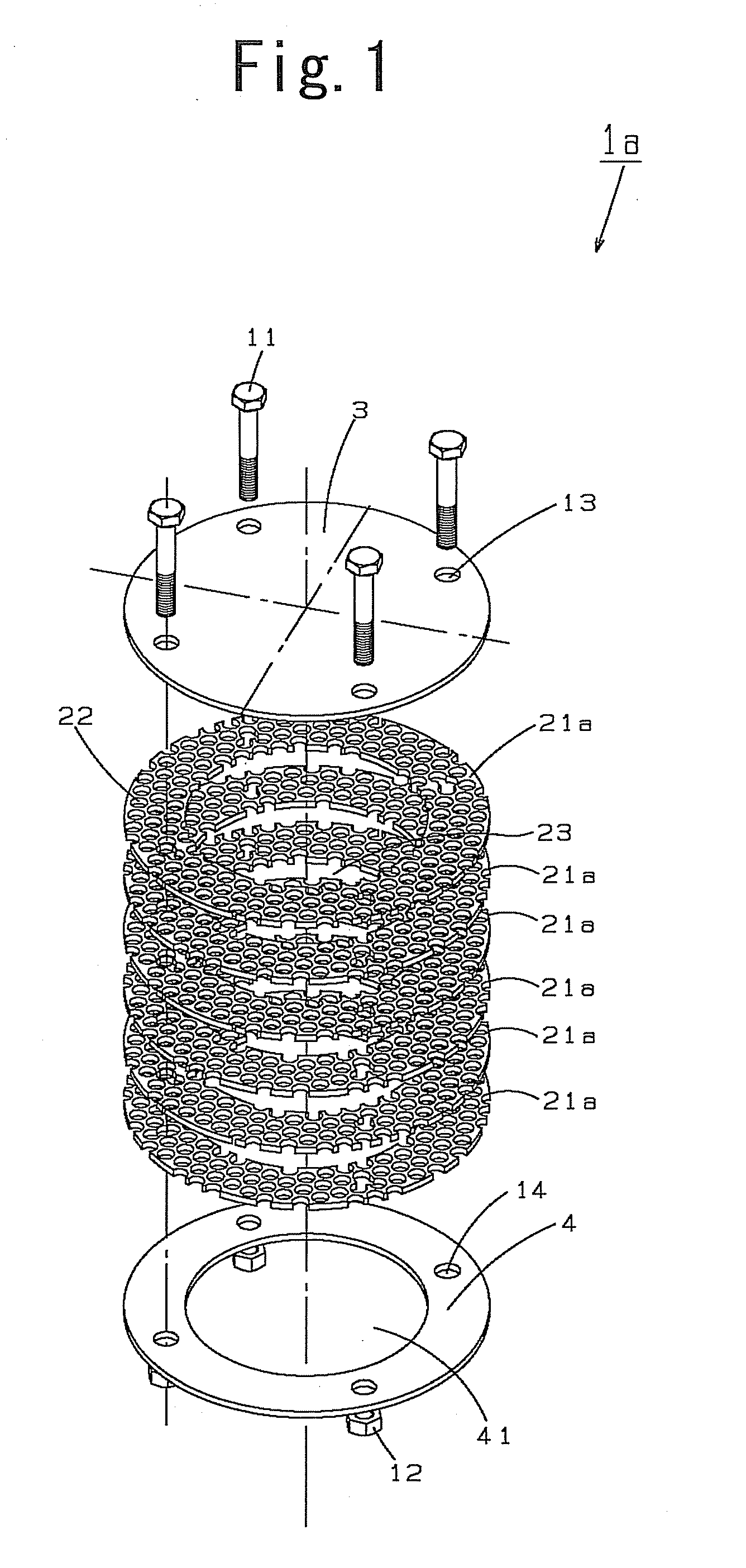
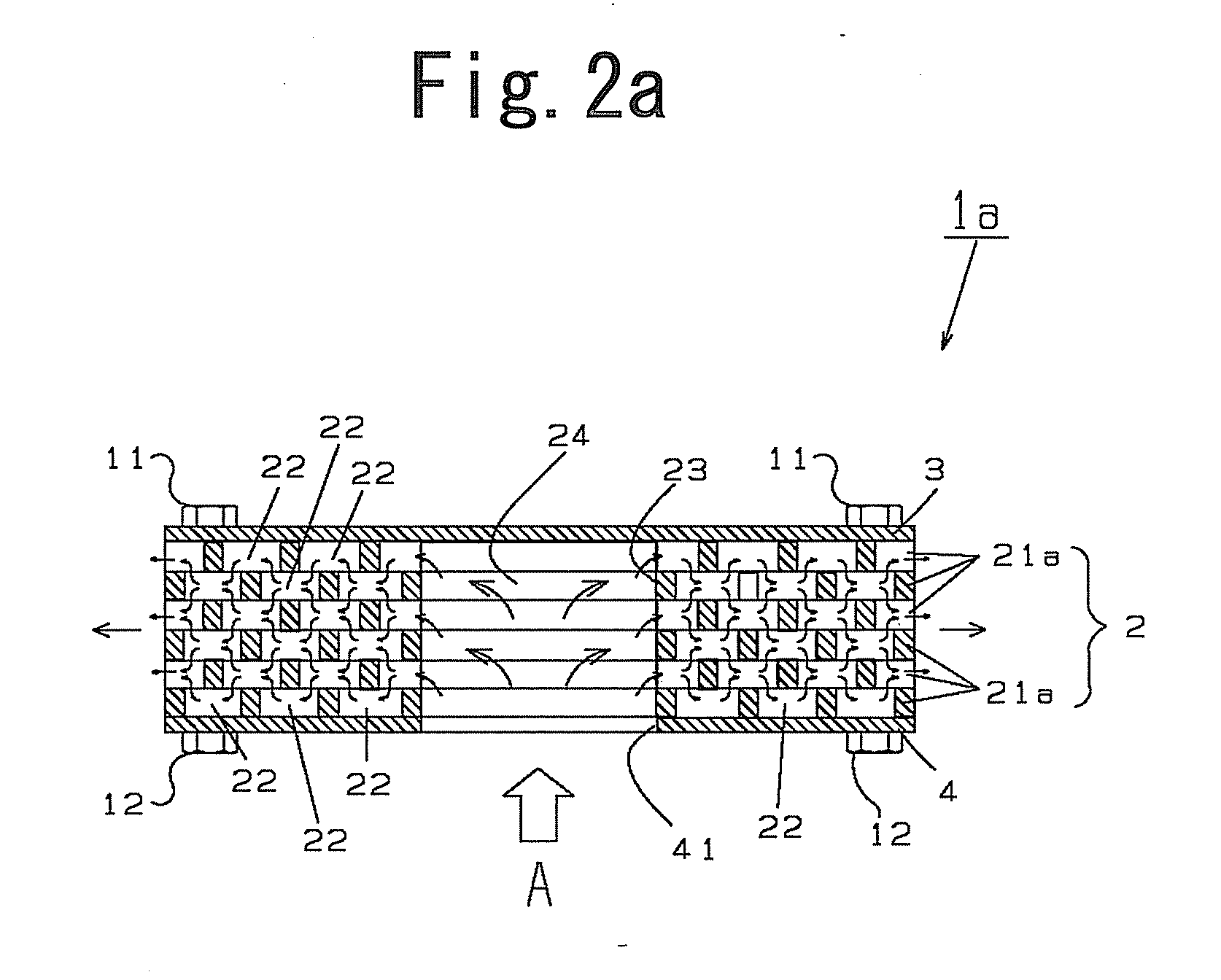
[0078]FIG. 1 is a perspective view showing the constituent components of a mixing unit 1a according to a first embodiment. FIG. 2(a) is a cross-sectional view showing how a fluid A flows through the mixing unit 1a; FIG. 2(b) is a plan view showing the stacked state of first through holes 22 when a mixing element 21a is placed on the adjacent mixing element 21a.

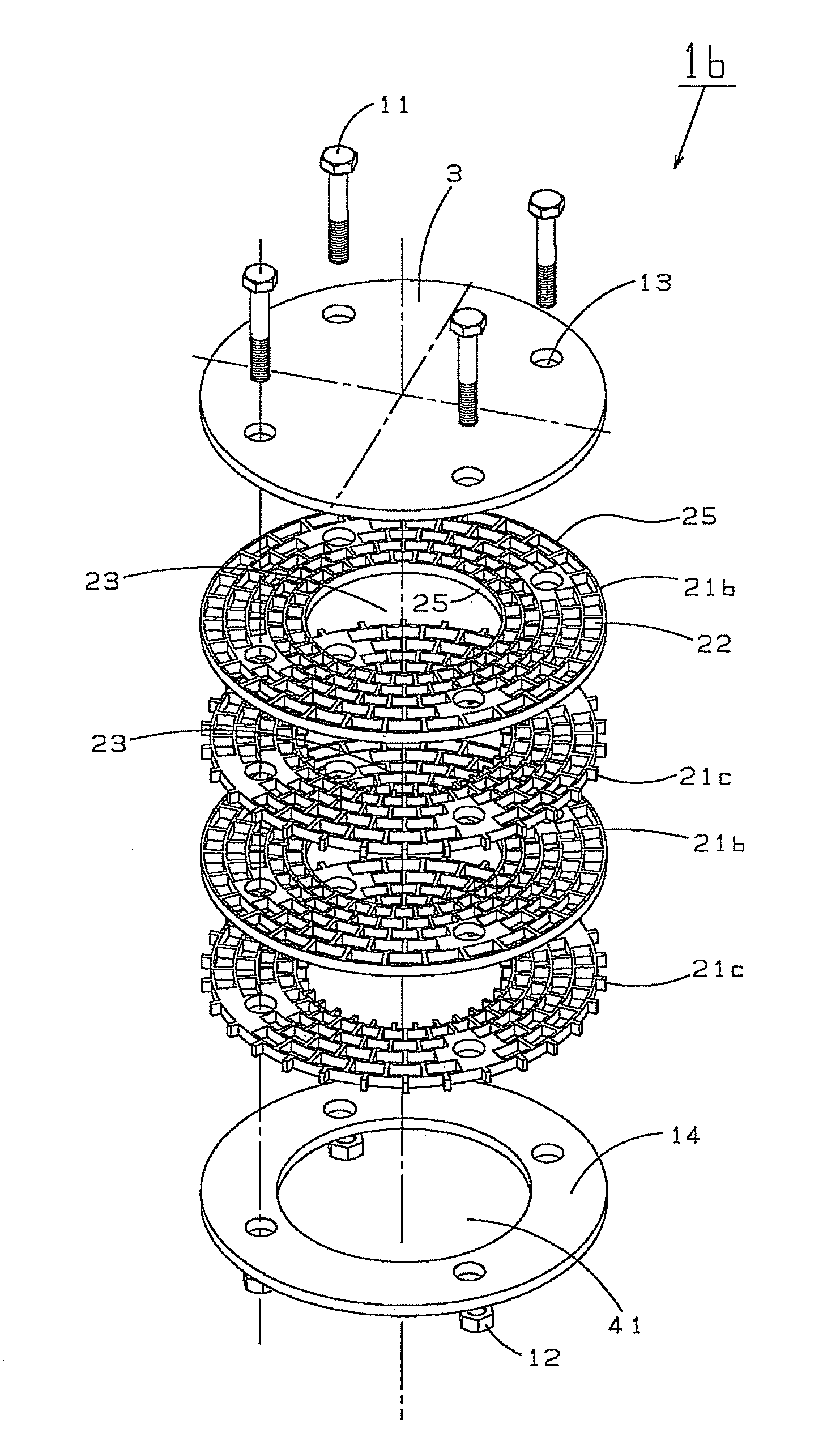
[0079]As shown in FIGS. 1 and 2, the mixing unit 1a is configured by sandwiching a stacked member 2, in which a plurality of disc-shaped mixing elements 21a (here, six mixing elements) are stacked, between a first plate 3 and a second plate 4 with, for example, fixed by four bolts 11 and nuts 12 appropriately arranged.

[0080]The first plate 3 is a disc having only holes 13 for the bolts. The second plate 4 has the holes 14 for the bolts and a circular opening portion 41 in the middle through which the fluid A flows. The first plate 3 and the second plate 4 are substantially equal in outside diameter to the mixi...

second embodiment

(Second Embodiment of the Pump Mixer)

[0157]FIG. 12 is a diagram showing a pump mixer 7b according to a second embodiment of the pump mixer. FIG. 12(a) is a cross-sectional view taken along line I-I of FIG. 12(b); FIG. 12(b) is a cross-sectional view showing how the fluid C flows through the pump mixer 7b.

[0158]The pump mixer 7b differs from the pump mixer 7a of the first embodiment in that the outer circumferential shape of the first plate 3 and the second plate 4 is larger than that of the mixing elements 21e and 21f, and that blades 76 (here, six blades) extending in the direction in which the mixing elements 21e and 21f are stacked are provided in a space formed by the first plate 3 and the second plate 4, that is, the outer circumferential portion of the stacked member 2.

[0159]When the mixing unit 1 rotates, the fluid C that has flowed out of the outer circumferential portion of the stacked member 2 flows out of the mixing unit 1 by receiving a force from the blades 76. Since t...


PUM

PropertyMeasurementUnit
shapeaaaaaaaaaa
diameteraaaaaaaaaa
areaaaaaaaaaaa

Abstract

A mixing unit, a mixing device, an agitation impeller and a pump mixer can mix a large amount of fluid while having significant mixing effects in a small space. There are also provided a mixing system that uses the pump mixer and achieves a continuous operation and a reaction device that uses the mixing unit and achieves an efficient operation. The mixing unit (1) includes: a stacked member (2) in which a plurality of mixing elements (21) are stacked; and a first plate (3) and a second plate (4) between which the stacked member (2) is sandwiched and which are arranged opposite each other. In the mixing unit (1), the mixing elements (21) have a plurality of first through holes (22), the second plate (4) has an opening portion (41) communicating with at least one of the first through holes (22) in the mixing elements (21) and the mixing elements (21) are arranged such that part or all of the first through holes (22) in one of the mixing elements (21) communicate with a first through hole (22) in the adjacent mixing element (21) to allow fluid to be passed in a direction in which the mixing elements (21) extend.

Description

TECHNICAL FIELD[0001]The present invention relates to a product that is applied as a mixing unit or a mixing device and is thus utilized to perform processing such as for statistically mixing fluid. The invention also relates to a product that is applied as an agitation impeller, a pump mixer or a mixing system and is thus utilized to perform processing such as for dynamically mixing fluid. The invention also relates to a product that is applied as a reaction device and is thus utilized to perform processing such as for efficiently mixing fluid to produce reaction.BACKGROUND ART[0002]As a static mixing device for mixing fluid, a Kenics-type static mixer or the like is widely used. Since this type of static mixer generally does not include a movable component, the static mixing device is widely used in fields, such as the chemical industry and the food industry, in which fluid is required to be mixed in piping. On the other hand, as a dynamic mixing device, a product is widely used t...

Claims


Application Information

Patent Timeline
Patent Type & Authority Applications(United States)
IPC IPC(8): B01J19/18B01F5/06B01F7/00B01F5/12B01F25/60B01F27/91B01F27/93B01F27/96
CPCB01F5/0604B01F7/00491B01F7/32B01J8/0292B01J8/04B01J8/0453B01J2219/00779B01J19/006B01J19/0066B01J19/1806B01J19/2405B01J2208/00849B01J2219/00777B01J8/0492B01F25/422B01F27/1155B01F27/96B01J19/00B01F23/20B01F25/40B01F27/91
Inventor MOCHIZUKI, NOBORU
Owner ISEL CO LTD
Learn More