
Method and system for managing data transmission from a plurality of sensor devices included in a tyre

a technology of sensor devices and tyres, applied in the direction of vehicle tyre testing, roads, instruments, etc., can solve the problems of devices with a very limited available power, and achieve the effect of precise monitoring of the contact region

Active Publication Date: 2011-04-14
PIRELLI TYRE SPA
View PDF7 Cites 26 Cited by
  • Summary
  • Abstract
  • Description
  • Claims
  • Application Information

AI Technical Summary

Benefits of technology

[0020]A reliable collection of data from a plurality of sensor devices included within a tyre should as much as possible avoid collisions between information (typically sent in form of data packets) sent from different sensor devices at the same time. In fact, collisions between packets sent from different sensor devices requires multiple retransmission of the missed packets, and / or multiple transmissions of all the packets from the sensor devices, which appears to be disadvantageous for devices which have a very limited available power. This latter issue becomes even more critical in case of use of energy scavenging components for the powering of the sensor devices, as it may be the case of a tyre integrated sensor system in which use of non-rechargeable and disposal-problematic batteries is refrained.
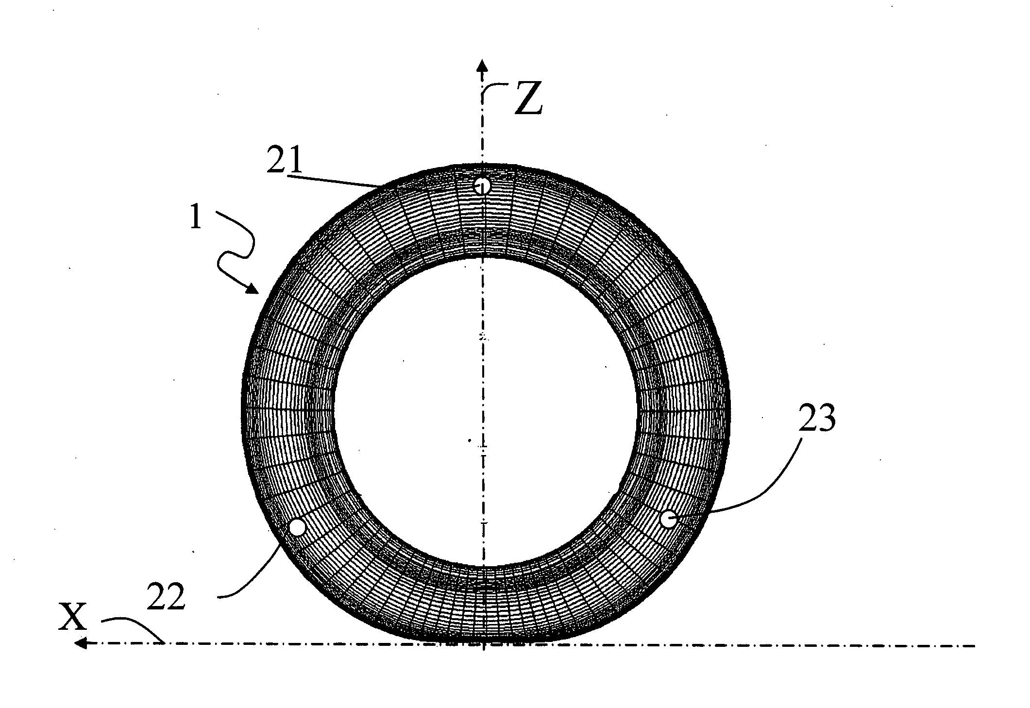
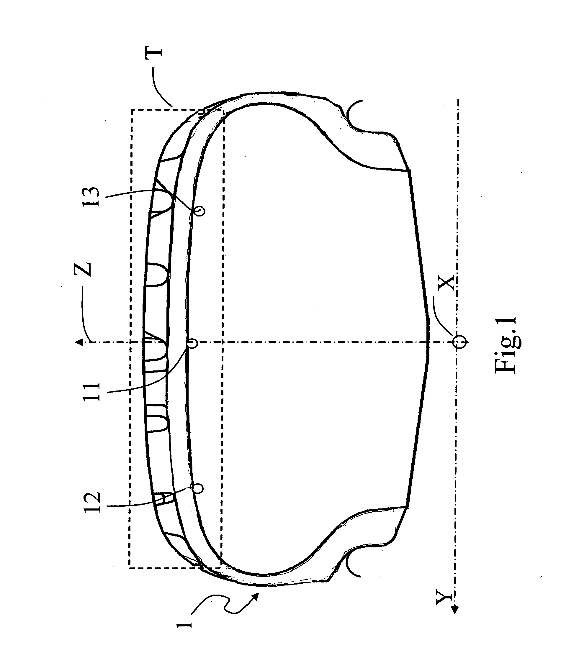
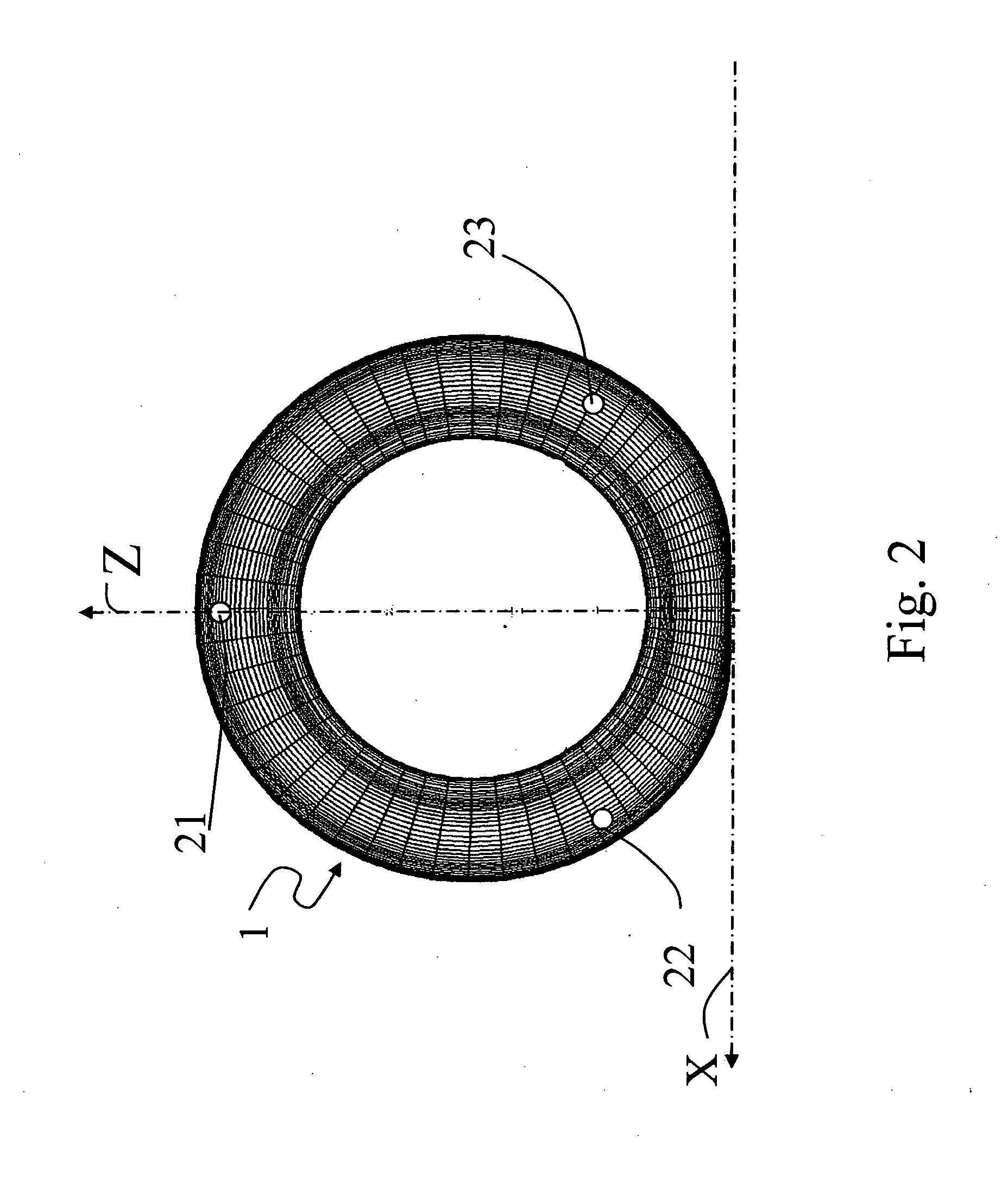
[0048]In preferred embodiments, the plurality of sensor devices comprises at least two sensor devices disposed substantially at the same meridian plane of the tyre (e.g. the sensor devices may be disposed within a circumferential angle of at most 5°). This allows a very precise monitoring of the contact region between the tyre and the ground.

Problems solved by technology

In fact, collisions between packets sent from different sensor devices requires multiple retransmission of the missed packets, and / or multiple transmissions of all the packets from the sensor devices, which appears to be disadvantageous for devices which have a very limited available power.
This latter issue becomes even more critical in case of use of energy scavenging components for the powering of the sensor devices, as it may be the case of a tyre integrated sensor system in which use of non-rechargeable and disposal-problematic batteries is refrained.
The Applicant has thus faced the problem of providing a reliable and low power consuming transmission from a plurality of sensor devices included within a tyre.

Method used


Image

  • Method and system for managing data transmission from a plurality of sensor devices included in a tyre
  • Method and system for managing data transmission from a plurality of sensor devices included in a tyre
  • Method and system for managing data transmission from a plurality of sensor devices included in a tyre

Examples


example 1

[0096]FIG. 3 shows a first exemplary sequence of time frames for the coordinated data transmission of three nodes / sensor devices located on the same meridian plane of a tyre. It is assumed that a beacon (represented by “B” in FIG. 3) including timing information is sent by a transmission coordinator associated to the three nodes / sensor devices at the beginning of a time window provided for data transmission. It is also assumed that data acquisition is performed in a different time window.

[0097]As shown by FIG. 3, the transmission coordinator sends a first beacon with timing information. The first beacon is correctly received by Node 2, but not received by Node 1 (designated as Master Node) and by Node 3 (as represented by the two “X”s in the first frame of FIG. 3). Thus, the transmission coordinator, the Node 1 and the Node 3 remain in a wait / listen mode for all the first frame, while the Node 2 calculates and waits for its assigned timeslot in the first frame, in which it transmits...

example 2

[0100]FIG. 4 shows a second exemplary sequence of time frames for the coordinated data transmission of three nodes / sensor devices located on the same meridian plane of a tyre. It is assumed that a beacon (represented by “B” in FIG. 4) including timing information is sent three times by a transmission coordinator associated to the three nodes / sensor devices at the beginning of a time window provided for data acquisition. It is also assumed that data transmission is performed after the end of data acquisition.

[0101]The timing of the start of the transmission window could be dictated by a suitable parameter T —tx included in the beacon. The beacon including timing information is sent three times in sequence by the transmission coordinator in order to reduce (or even nullify) the probability of non-reception of the beacon by the nodes / sensor devices. In this exemplary communication protocol, in fact, the transmission coordinator does not have an acknowledgement of the reception of the b...

example 3

[0103]FIG. 5 shows a third exemplary sequence of time frames for the retransmission of lost data packets transmitted by three nodes / sensor devices located on the same meridian plane of the tyre. It is assumed that the communication protocol provides for a retransmission window at the end of the transmission window. For example, such retransmission window could last 10% of the transmission window. The timing information for enabling the nodes / sensor devices to correctly set the retransmission window could be sent in the beacon sent by the transmission coordinator or permanently stored in the memory of the nodes / sensor devices. However, differently from the transmissions of the data packets, retransmissions do not follow a TDMA schedule, but are performed by the nodes / sensor devices on request received by the transmission coordinator.

[0104]It is assumed that at the end of the transmission window each node / sensor device switches on its respective receiver for listening for possible ret...


PUM


Abstract

Wireless transmission from sensor devices included in tyres is coordinated by a receiving unit associated with the tyre, or transmission coordinator. In more detail, every sensor device is made aware of an overall time window available for transmission, and based on at least this information, it calculates a dedicated timeslot for the transmission of its data within such time window. This coordinated transmission makes possible a strong reduction of the probability of collisions and transmission errors, and reduces the number of transmissions, so as to comply with the limited power resources available at each sensor device.

Description

FIELD OF THE INVENTION[0001]The present invention relates to a method and a system for managing transmission of data measured by a plurality of sensors included in a tyre fitted on a vehicle. Said sensors could comprise for example accelerometers, and / or strain gauges, and / or pressure sensors, and / or temperature sensors.BACKGROUND OF THE INVENTION[0002]The incorporation of electronic devices within pneumatic tyres is taking a greater importance in order to increase safety of vehicles. Tyre electronics may include sensors and other components suitable for obtaining information regarding the behavior of a tyre, as well as various physical parameters thereof, such as for example temperature, pressure, number of tyre revolutions, vehicle speed, etc. Such information may become useful in tyre monitoring and / or alarm systems. Furthermore, active control systems of the vehicle may be based on information sent from sensor devices included within the tyres.[0003]Integrated tyre electronics s...

Claims


Application Information

Patent Timeline
IPC IPC(8): B60C23/00G06F19/00G01M17/02
CPCB60C23/0461B60C23/0462B60T8/1725B60C23/064B60C23/0464
Inventor EREGEN, SINEM COLERISUN, XUENING
Owner PIRELLI TYRE SPA
Learn More