
Ground Vehicle Collision Prevention Systems and Methods

Active Publication Date: 2011-04-14
THE BOEING CO
View PDF35 Cites 42 Cited by
  • Summary
  • Abstract
  • Description
  • Claims
  • Application Information

AI Technical Summary

Benefits of technology

[0009]The present invention comprises systems and methods for preventing collisions between aircraft and ground vehicles. In one aspect, a ground vehicle collision prevention system includes a proximity detection system positioned on an aircraft and coupled to at least one transducer proximate to at least one selected structural portion of the aircraft. The proximity detection system is operable to emit ranging signals through the at least one transducer and to receive reflected signals through the at least one transducer to determine the position of an object within a ranging area adjacent to th

Problems solved by technology

Accordingly, relatively long turnaround times are often encountered in the operation of passenger aircraft, which adversely affects the return on investment for an aircraft operator since the aircraft cannot generate revenue while sitting on the ground.
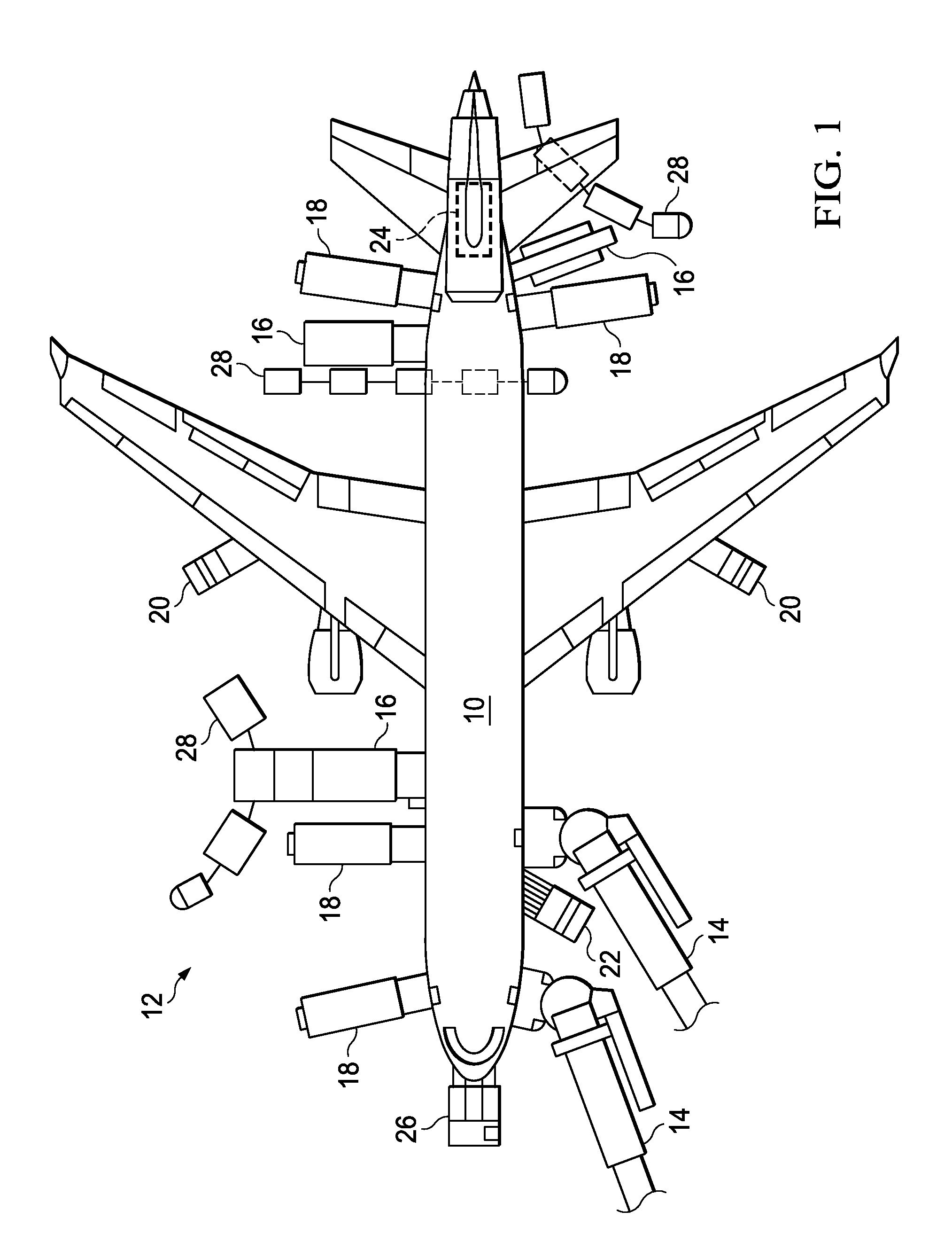
A risk therefore exists that a service vehicle may inadvertently collide with a portion of the aircraft 10 while moving about the aircraft 10.
Such a collision may result in significant damage to the aircraft 10, requiring a costly and time-consuming repair before the aircraft 10 is returned to service.
Damage to non-metallic composite components may be costly to repair.
Moreover, selected portions of the aircraft 10 are particularly susceptible to damage while the aircraft 10 is positioned on the ground.
For example, landing gear doors, cargo loading doors and passenger access doors are generally maintained in an open position during ground operations, and may be relatively easily damaged by even a minor collision.
Even in cases where damage to the aircraft 10 is less significant, relatively expensive flight delays are often incurred since a mandated inspection of the damaged area must be performed to determine if the damage is within allowable limits.

Method used


Image

  • Ground Vehicle Collision Prevention Systems and Methods
  • Ground Vehicle Collision Prevention Systems and Methods
  • Ground Vehicle Collision Prevention Systems and Methods

Examples


Embodiment Construction

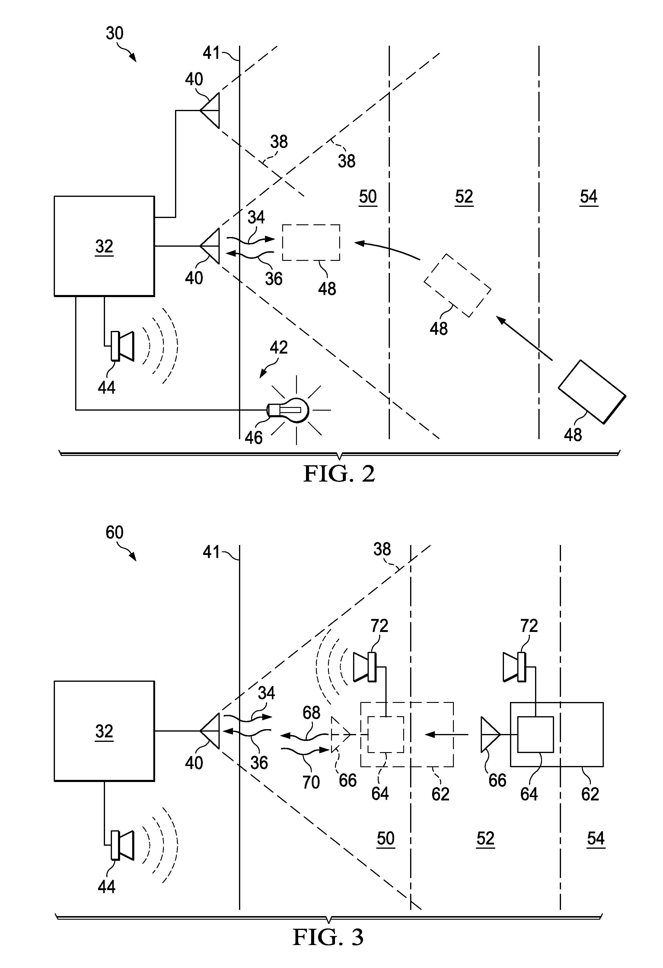
[0024]The present invention relates to ground vehicle collision prevention systems and methods. Many specific details of certain embodiments of the invention are set forth in the following description and in FIGS. 2 through 9 to provide a thorough understanding of such embodiments. One skilled in the art, however, will understand that the present invention may have additional embodiments, or that the present invention may be practiced without several of the details described in the following description.

[0025]FIG. 2 is a block diagrammatic view of a ground vehicle collision prevention system 30 according to an embodiment of the invention. The system 30 includes a proximity detection system 32 operable to generate ranging signals 34 and to detect return signals 36 reflected from objects positioned within a ranging area 38. The proximity detection system 32 is further coupled to at least one transducer 40 (two shown) that is positioned proximate to an aircraft structural portion 41. T...


PUM


Abstract

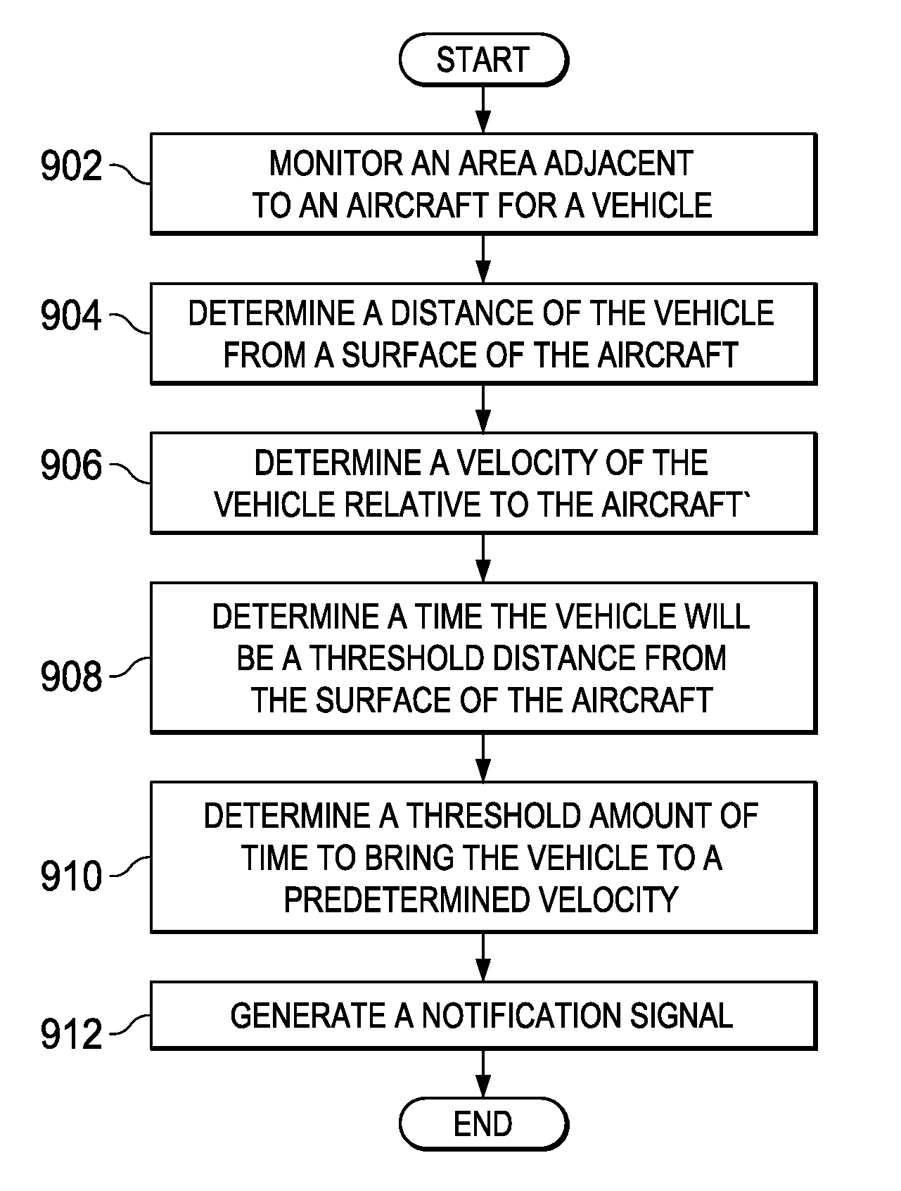
A method and apparatus for detecting a vehicle. An apparatus comprises a proximity detection system, a vehicle management system, and a notification system. The proximity detection system is associated with an aircraft and operably connected to a transducer. The proximity detection system is configured to determine a distance of a vehicle from a surface of the aircraft and a velocity of the vehicle relative to the aircraft. The vehicle management system operably connected to the proximity detection system. The vehicle management system is configured to determine a time the vehicle will be a threshold distance from the surface of the aircraft and an threshold amount of time to bring the vehicle to a predetermined velocity. The notification system is associated with the proximity detection system and configured to generate a notification signal in response to a determination that the time is less than the threshold amount of time.

Description

[0001]This application is a continuation-in-part of application Ser. No. 12 / 538,441, filed Aug. 10, 2009, status pending, which is herein incorporated by reference. Application Ser. No. 12 / 538,441 is a division of U.S. Pat. No. 7,379,165 filed Sep. 30, 2004 which is here incorporated by reference.BACKGROUND INFORMATION[0002]1. Field[0003]This invention relates generally to aircraft ground operations, and more particularly to ground vehicle collision prevention systems and methods.[0004]2. Background[0005]Passenger aircraft generally require the performance of a variety of different tasks following the termination of a specific flight. For example, the aircraft must be refueled, cargo must be unloaded, the cabin of the aircraft must be cleaned, the lavatory wastewater must be removed, and the galley must be re-provisioned, among other tasks. Accordingly, relatively long turnaround times are often encountered in the operation of passenger aircraft, which adversely affects the return o...

Claims


Application Information

Patent Timeline
IPC IPC(8): G05D1/00G01S13/931G01S13/934
CPCB60Q1/48B60Q1/525B60Q5/006B64F1/3055G01S13/58G01S2013/9364G01S2013/9335G01S2013/9367G08G1/163G08G5/0078G01S2013/936G01S13/931G01S13/934G01S2013/9316G01S2013/9324G01S2013/9323
Inventor ANDERSON, DAVID M.BANKS, DAVID L.AVERY, ROBERT L.AKDENIZ, AYDIN
Owner THE BOEING CO
Learn More