Eddy-free high velocity cooler

a high-speed cooler and eddy-free technology, applied in the field of eddy-free high-speed coolers, can solve the problems of inconvenient drilling, other devices can generate enough heat that will destroy themselves, and drilling is usually not appropria

Inactive Publication Date: 2011-04-21
MACRAE ALLAN J
View PDF2 Cites 56 Cited by
  • Summary
  • Abstract
  • Description
  • Claims
  • Application Information

AI Technical Summary

Benefits of technology

[0038]A principal advantage of the present invention is that workpiece embodiments will have an extended service life that can be budgeted and maintained in a step 226.

Problems solved by technology

Engines and other devices can generate enough heat that will destroy themselves if cooling were not used to keep the operating temperatures within acceptable limits.
Drilling is usually not appropriate when complex cooling patterns are needed, so drilling has been limited to straight line passages.
The amount of cooling possible in cast-in-pipe implementations is further limited by standard bend dimensions.
The round cross section of pipes further reduces the effective cooling channel area, and thus the flow volume.
However, these simple designs can produce significant eddies in the coolant flow just past where the coolant is turned in each loop, and problems in cooling uniformity due to these eddies are amplified when the coolant velocity is pushed to high levels.
However, the flow regime within the fluid coolant in conventional castings is typically quite poor.
The heat at those spots can build up high enough to boil the coolant, and that can lead to the failure of the part and the connecting piping.

Method used


Image

  • Eddy-free high velocity cooler
  • Eddy-free high velocity cooler
  • Eddy-free high velocity cooler

Examples


Embodiment Construction

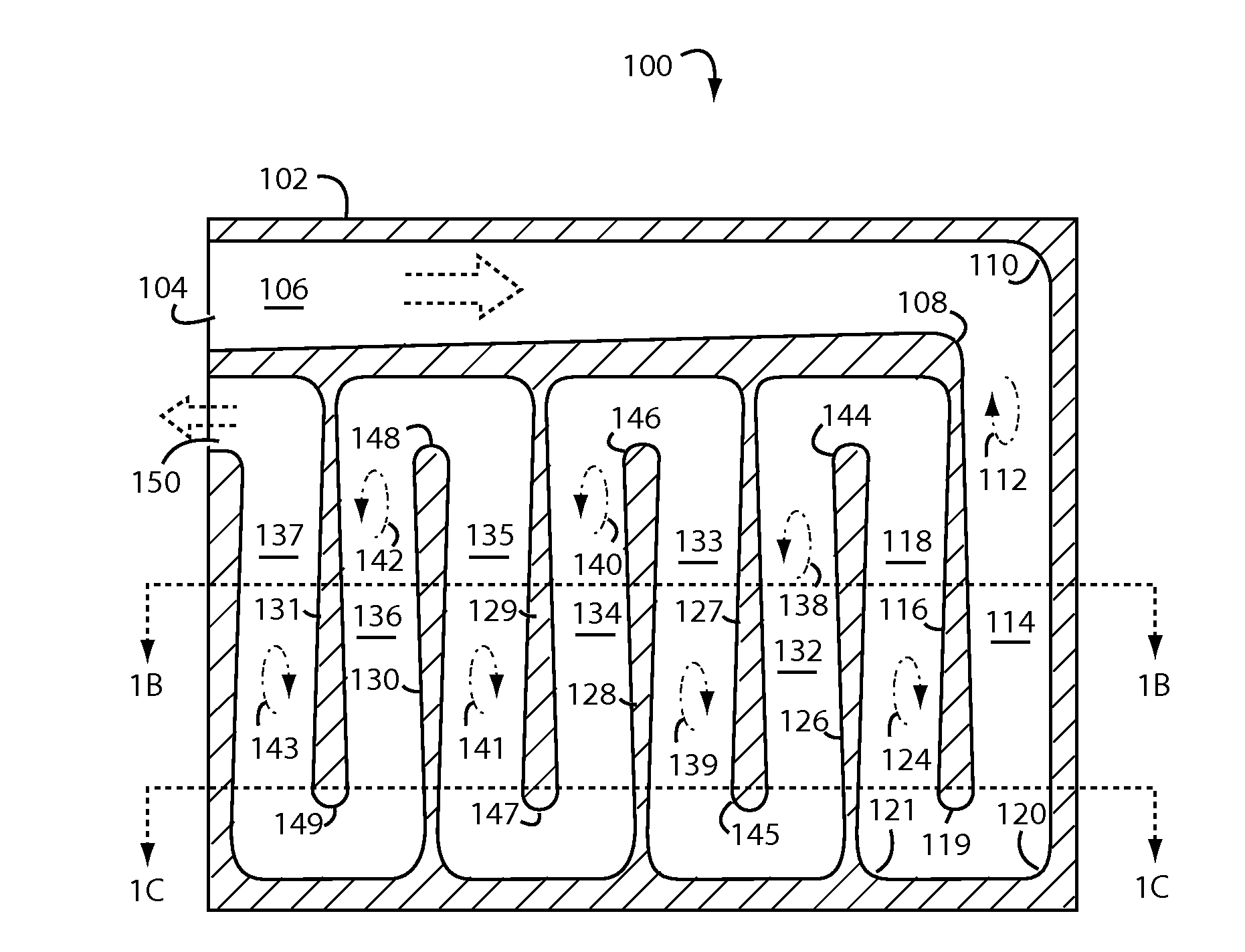
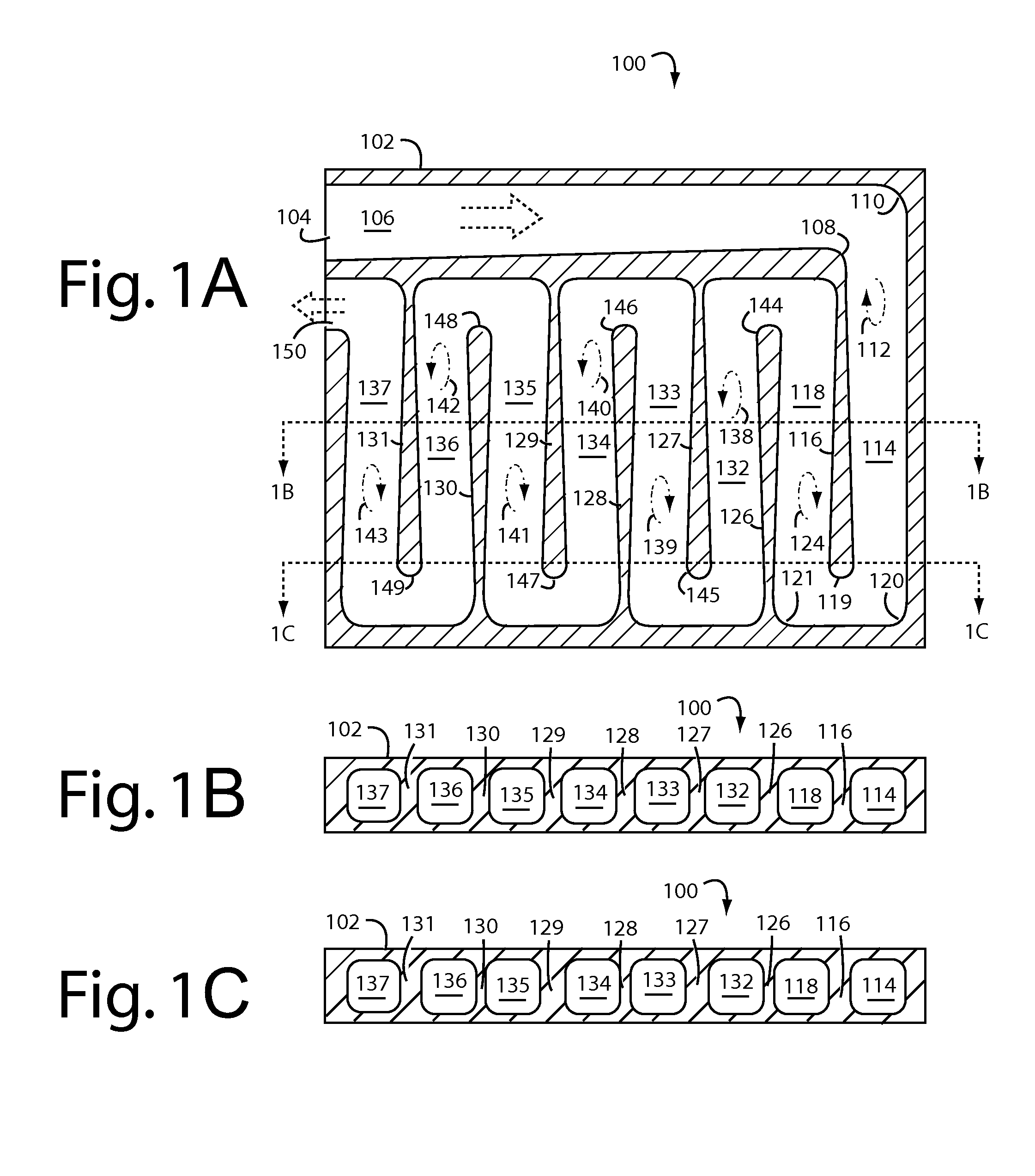
[0029]FIGS. 1A-1C represents a cooling system embodiment of the present invention, and is referred to herein by the general reference numeral 100. Cooling system 100 comprises a cast metal workpiece 102 with an inlet 104 to a serpentine passageway 106 for a circulating fluid coolant. A first turn in the serpentine passageway 106 has an inside turn radius 108 and an outside turn radius 110 with respect to the general plane of the serpentine passageway 106. The inside and outside turn radii 108 and 110 are dimensioned and shaped to eliminate eddies 112 in the coolant flow at these points and just downstream.

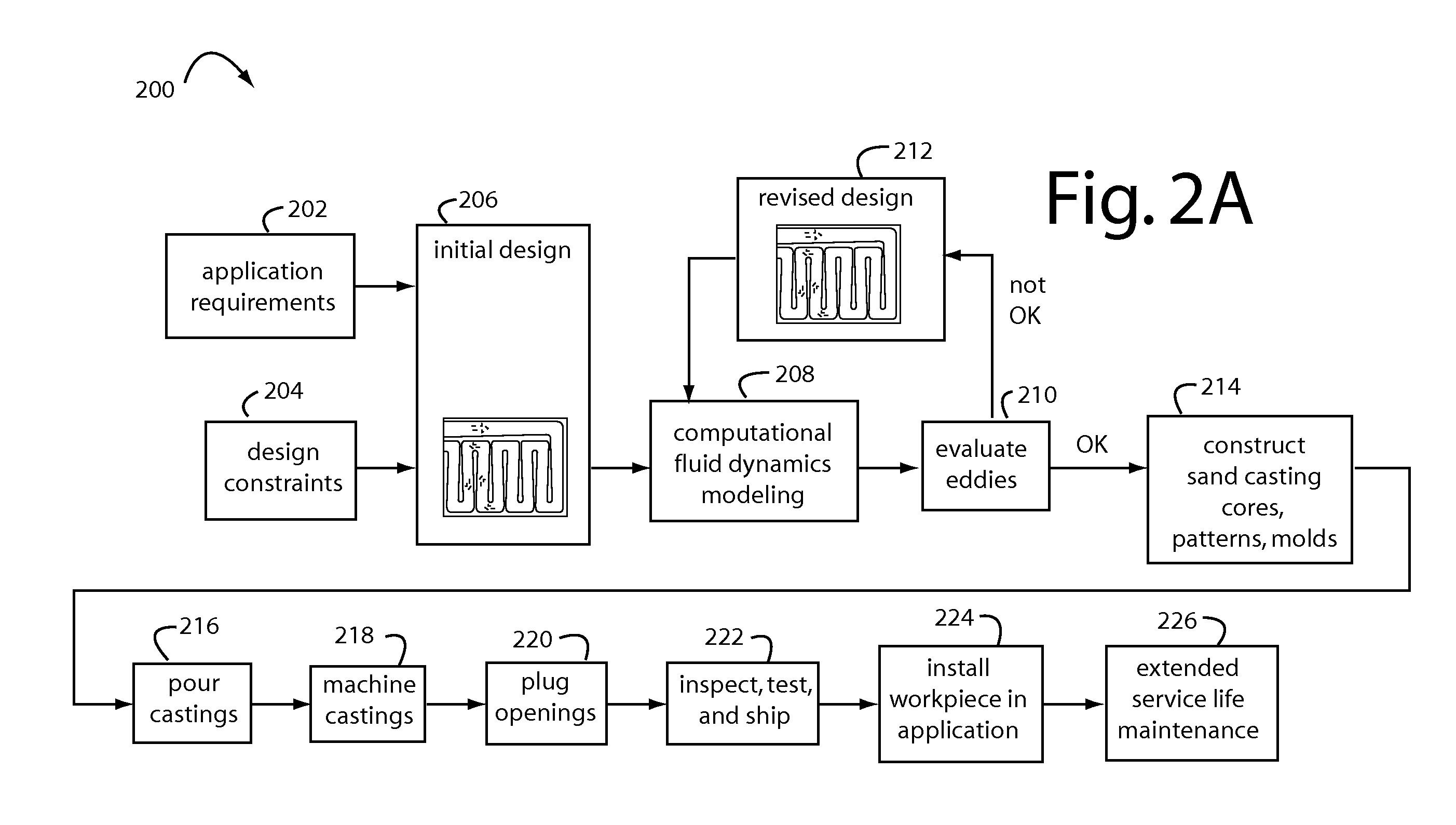
[0030]In general, making the turning radii broader and wider will, at some point, eliminate eddies 112 in the coolant flow, but this must be balanced with the negative effects that thickening the walls of casting material to accommodate the rounded geometry will have on heat transfer performance. One way to find the optimum balance point is to employ computational fluid dynamics mo...


PUM

PropertyMeasurementUnit
operating temperaturesaaaaaaaaaa
diameteraaaaaaaaaa
diameteraaaaaaaaaa

Abstract

A cooling system comprises serpentine cooling fluid passages cast into a work piece with carefully controlled turning radii and profiles. Individual interdigitated baffles are contoured in the plane of coolant flow to have walls that thicken and then round off at their distal ends. The outside radii at these turns is similarly rounded and controlled such that the coolant flow will not be swirled into eddies.

Description

BACKGROUND[0001]1. Field of the Invention[0002]The present invention relates to gas and fluid cooling of equipment, and more particularly to methods and devices for eliminating eddy currents in high velocity coolant flows through serpentine passageways.[0003]2. Description of the Prior Art[0004]Cooling is widely used in equipment and machines of all sizes and descriptions. Three modes of cooling, or heat transfer, depend on thermal radiation, heat conduction, and heat convention. Engines and other devices can generate enough heat that will destroy themselves if cooling were not used to keep the operating temperatures within acceptable limits. Radiators in cars are a familiar way that water coolants are circulated through a gas engine to keep its operating temperatures under 200° F. The excess heat is transferred to the air blowing through the engine compartment.[0005]Fluid and gas-cooled castings and machined coolers are widely used in the roofs, walls and hearths of metallurgical f...

Claims


Application Information

Patent Timeline
Patent Type & Authority Applications(United States)
IPC IPC(8): C21B7/00F28D15/00B23P15/26C21B7/16F23L5/00
CPCC21B7/10C21B7/163F27B1/16F27B1/24Y10T29/49341F28F3/12F28F7/02F28F13/02Y10T29/49359F27D9/00C21B7/00C21B7/16
Inventor MACRAE, ALLAN J.
Owner MACRAE ALLAN J
Why Eureka
Try Eureka