Semiconductor device with a balun

a technology of semiconductor devices and baluns, which is applied in the direction of semiconductor devices, semiconductor/solid-state device details, waveguides, etc., can solve the problems of imposing limitations in reducing the differential impedance zo, unable to be sufficiently narrow, and large losses of passive elements, such as transmission lines or inductors

Active Publication Date: 2011-04-21
PANASONIC CORP
View PDF9 Cites 5 Cited by
  • Summary
  • Abstract
  • Description
  • Claims
  • Application Information

AI Technical Summary

Benefits of technology

The present invention provides a semiconductor device with a wide-band and small-size balun. The device increases the electromagnetic coupling between the unbalanced line and the balanced lines of the balun without affecting other lines in different interconnect layers. This results in improved performance and reduced size of the semiconductor device.

Problems solved by technology

The technical problem addressed in this patent is the need to increase the bandwidth of a balun, which is a type of electronic component used for impedance conversion and signal transmission, in a way that is not affected by the low resistance of a semiconductor substrate. The solution involves forming the unbalanced and balanced interconnect films of the balun on different layers of the substrate, which allows for a greater degree of electromagnetic coupling and a decrease in differential impedance, thereby increasing the bandwidth of the balun.

Method used


Image

  • Semiconductor device with a balun
  • Semiconductor device with a balun
  • Semiconductor device with a balun

Examples


Embodiment Construction

[0037]Hereinafter, an embodiment of the present invention is described with reference to the drawings.

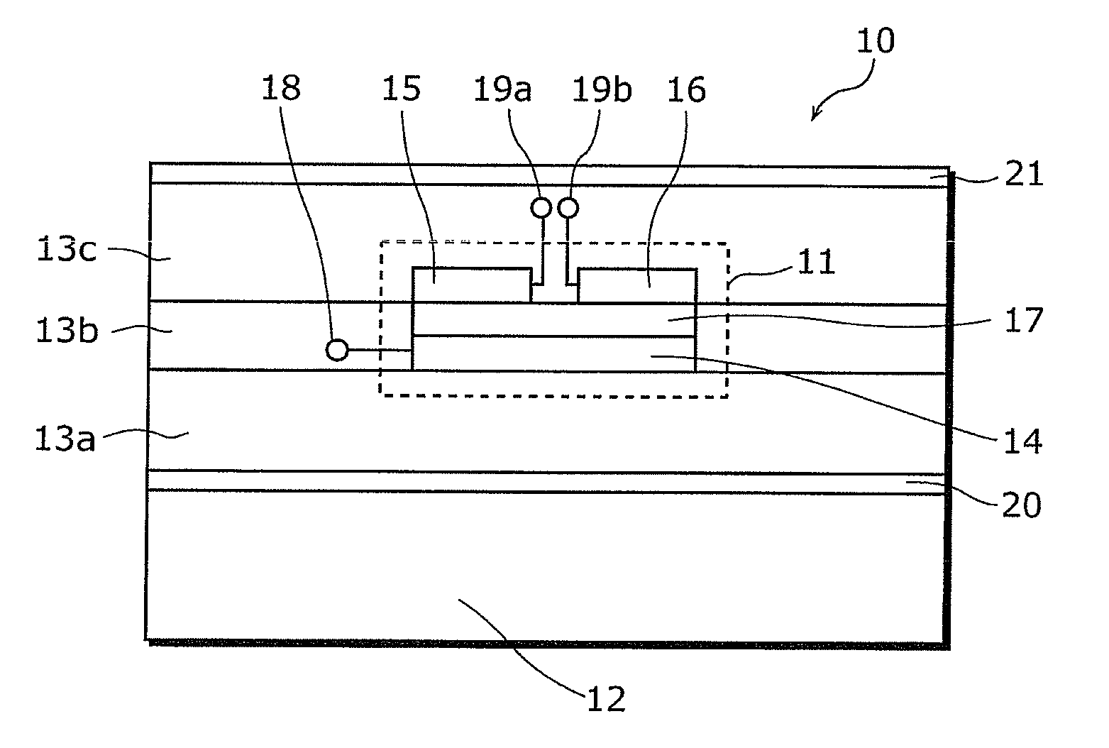
[0038]FIG. 1 is a cross sectional view showing an example of a structure of a semiconductor integrated circuit device 10 including a balun 11 according to the embodiment of the present invention.

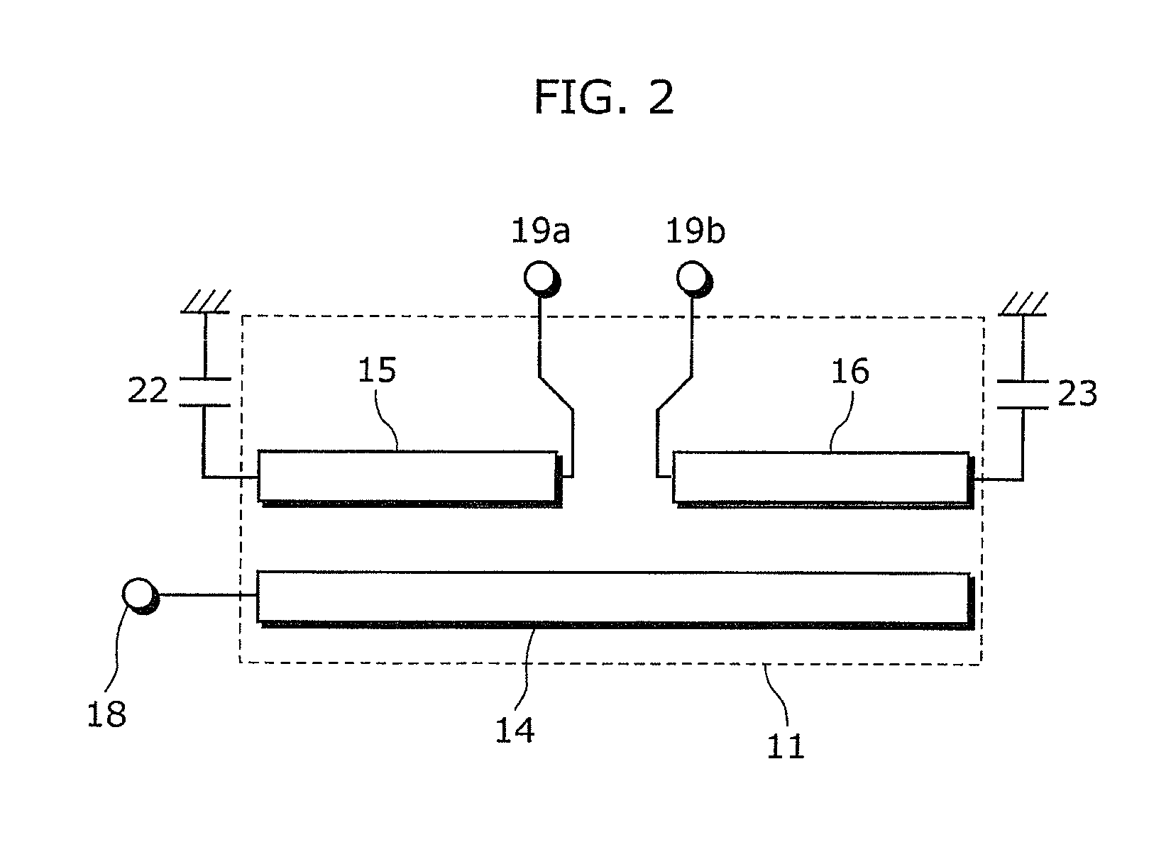
[0039]FIG. 2 is a circuit diagram showing a circuit structure of the balun 11 shown in FIG. 1.

[0040]The semiconductor integrated circuit device 10 shown in FIG. 1 includes: the balun 11, a semiconductor substrate 12, dielectric films 13a, 13b, and 13c, an unbalanced line 14 for transmitting an unbalanced signal, balanced lines 15 and 16 for transmitting a balanced signal, a nano-composite film (a high dielectric film) 17, an unbalanced signal input (output) terminal 18, balanced signal output (input) terminals 19a and 19b, and ground electrode films 20 and 21.

[0041]Above the semiconductor substrate 12, dielectric layers where dielectric films are provided and interconnect layers where interc...


PUM


Abstract

A semiconductor integrated circuit device with a balun which is formed above a conductive semiconductor substrate and which includes a dielectric film, an unbalanced line for transmitting an unbalanced signal, and balanced lines for transmitting a balanced signal. The unbalanced line is placed opposite to the balanced lines via a nano-composite film that is a region of the dielectric film. The nano-composite film, interposed between the unbalanced line and the balanced lines, has a relative permittivity higher than that of other regions of the dielectric film. This allows suppression of electromagnetic coupling of transmission lines or passive elements other than the balun, thereby providing a semiconductor device with a wide-band and small-size balun.

Description


Claims


Application Information

Patent Timeline
Owner PANASONIC CORP
Why Eureka
Try Eureka