Serial siphon valves for fluidic or microfluidic devices

a fluidic or microfluidic device technology, applied in the field of fluidic devices, can solve the problems of complex transducer systems, less reliable burst valves, and limited practical applications, and achieve the effect of saving radial space and more features

Active Publication Date: 2011-04-28
RGT UNIV OF CALIFORNIA +1
View PDF15 Cites 23 Cited by
  • Summary
  • Abstract
  • Description
  • Claims
  • Application Information

AI Technical Summary

Benefits of technology

[0009]It is a non-limiting object of the present invention to provide a method using a co-radial arrangement of siphon structures each separated by a capillary valve in a fluidic system. Such a method allows saving radial space. This saved radial space can be used, for example, to add more features on a fluidic device.
[0011]It is a non-limiting object of the present invention to provide a device using a co-radial arrangement of siphon structures each separated by a capillary valve in a fluidic system. Such a device allows saving radial space. This saved radial space can be used, for example, to add more features on a fluidic device.BRIEF SUMMARY OF THE INVENTION

Problems solved by technology

In general, burst valves are less reliable and thus have limited practical applications.
Mechanical valves of all types necessarily require transduction systems that are complicated and not as reliable as siphons.
When the centripetal G-force is higher than the capillary force, a capillary valve cannot prevent liquid movement within the system.
Therefore, capillary valves cannot be used to robustly delay liquid into a downstream chamber in such a system.

Method used


Image

  • Serial siphon valves for fluidic or microfluidic devices
  • Serial siphon valves for fluidic or microfluidic devices
  • Serial siphon valves for fluidic or microfluidic devices

Examples


example 1

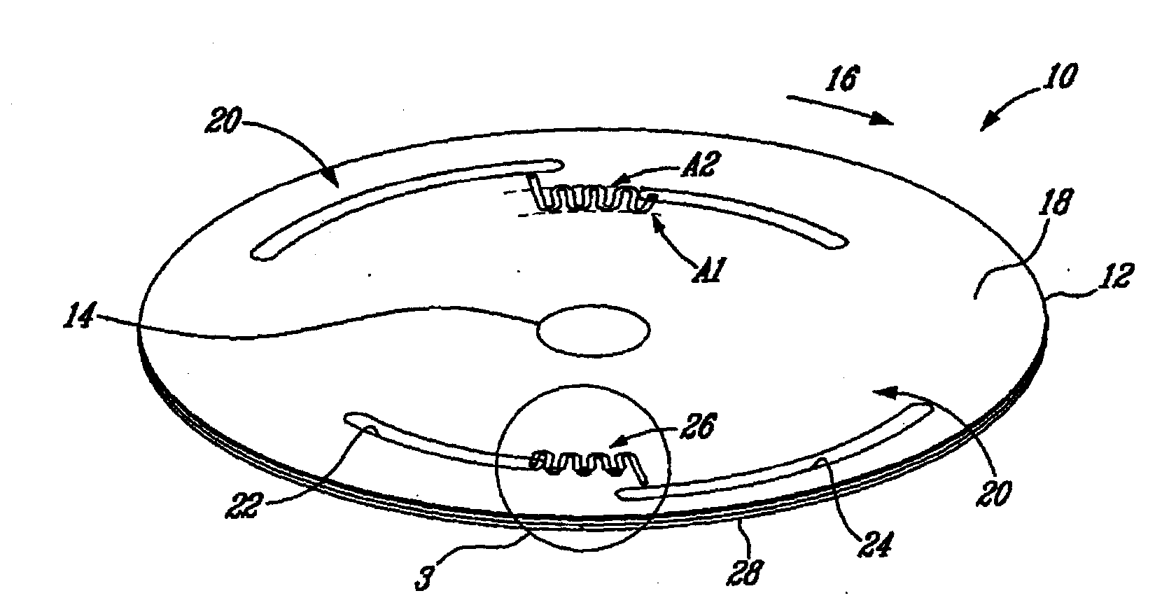
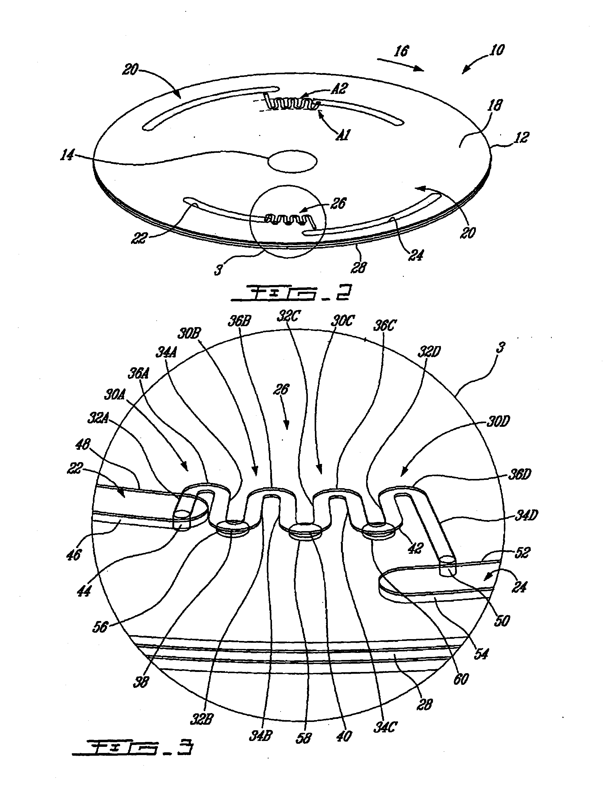
[0070]A serial arrangement of siphon valves in a centripetal fluidic platform for controlling the release of fluid.

[0071]FIGS. 7A to 7J illustrate the present invention in action. A non-limiting example of a corresponding spin profile is also shown in FIG. 8. More specifically, FIG. 8 illustrates the spin profile used to control the release of liquid L from an upstream chamber 22 into a downstream chamber 24 by the use of serial siphon microfluidic structures such as the serial siphon valve conduit 26.

[0072]Rotation at 1,500 RPM generates centrifugal acceleration that enables the liquid front to travel beyond the capillary valves. After about 24 seconds (see FIGS. 7J and 8), most of the liquid L from the upstream chamber 22 can be transferred to the downstream chamber 24. In this example a total of five cycles of rotation and stopping are demonstrated. The number of cycles that may be incorporated into this system would be limited by the liquid front's (F1, F2, F3, F4, F5, F6, F7, F...


PUM


Abstract

Methods and devices using a co-radial arrangement of serial siphon structures composed of siphon valves each separated by a capillary valve to save radial space in a fluidic system. Such serial siphon valves allow to sequentially distribute liquids in a fluidic system upon application of successive centripetal accelerations and decelerations applied to a rotary platform.

Description

CROSS-REFERENCE TO RELATED APPLICATIONS[0001]The present application requests priority on U.S. Provisional Application No. 60 / 904,372 filed in the United States Patent Office on Mar. 2, 2007 and incorporated herein by reference in its entirety.FIELD OF INVENTION[0002]The present invention relates to a fluidic device. More specifically but not exclusively, the present invention relates to serial siphon valves for a fluidic device.BACKGROUND OF THE INVENTION[0003]Control of the release of liquid from a fluidic chamber via a spinning rotor is a very important function in the area of centrifuged-based fluidic systems for applications such as immunoassays, nucleic acid analysis, biochemical tests, chemical tests and sample preparation. This is because it is often necessary to mix different reagents together at the appropriate time, either in parallel or in series.[0004]Solutions to this problem include the use of rotational frequency-dependent burst valves, standard siphons, or mechanica...

Claims


Application Information

Patent Timeline
Patent Type & Authority Applications(United States)
IPC IPC(8): F15D1/00
CPCB01L3/502738B01L2200/0621B01L2300/0803B01L2300/0861B01L2400/0409G01N21/07F16K99/0001F16K99/0021F16K99/0063F16K2099/0074F16K2099/0084B01L2400/0688Y10T137/2911Y10T137/87917Y10T137/0753Y10T137/218Y10T137/0989Y10T137/86928
Inventor BERGERON, MICHEL G.PEYTAVI, REGISKIDO, HORACIOMADOU, MARC
Owner RGT UNIV OF CALIFORNIA
Why Eureka
Try Eureka