High voltage resistance coupling structure

Inactive Publication Date: 2011-04-28
INFINEON TECH AUSTRIA AG
View PDF0 Cites 30 Cited by
  • Summary
  • Abstract
  • Description
  • Claims
  • Application Information

AI Technical Summary

Problems solved by technology

If the circuits are not isolated, unwanted current can flow in the circuits (e.g., a ground

Method used


Image

  • High voltage resistance coupling structure
  • High voltage resistance coupling structure
  • High voltage resistance coupling structure

Examples


Embodiment Construction

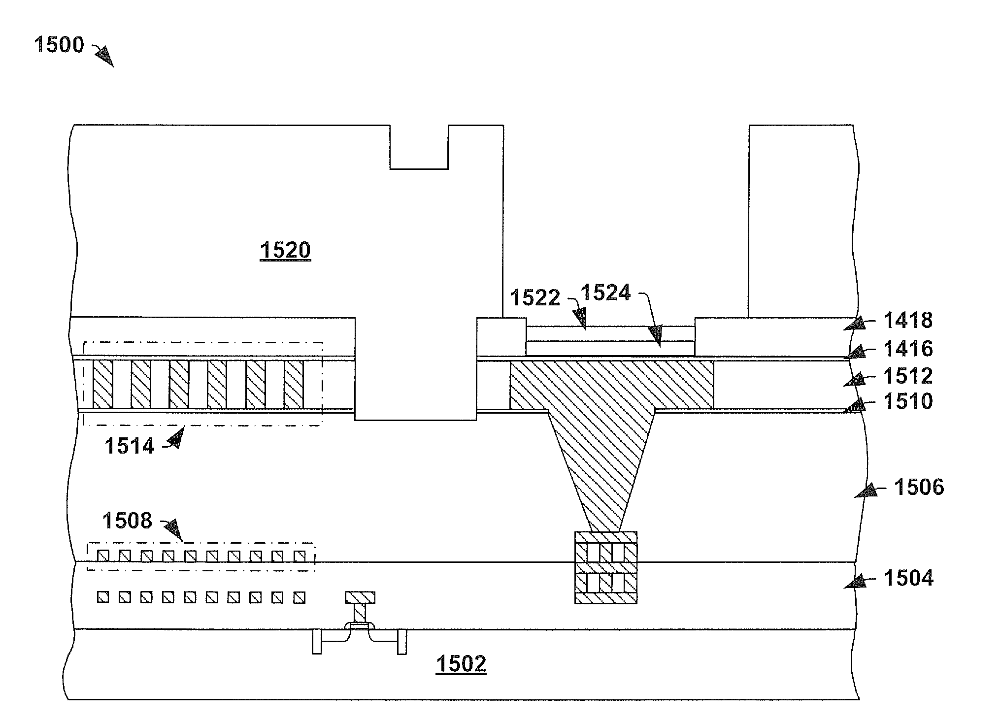
[0014]The present invention will now be described with reference to the attached drawing figures, wherein like reference numerals are used to refer to like elements throughout, and wherein the illustrated structures and devices are not necessarily drawn to scale.

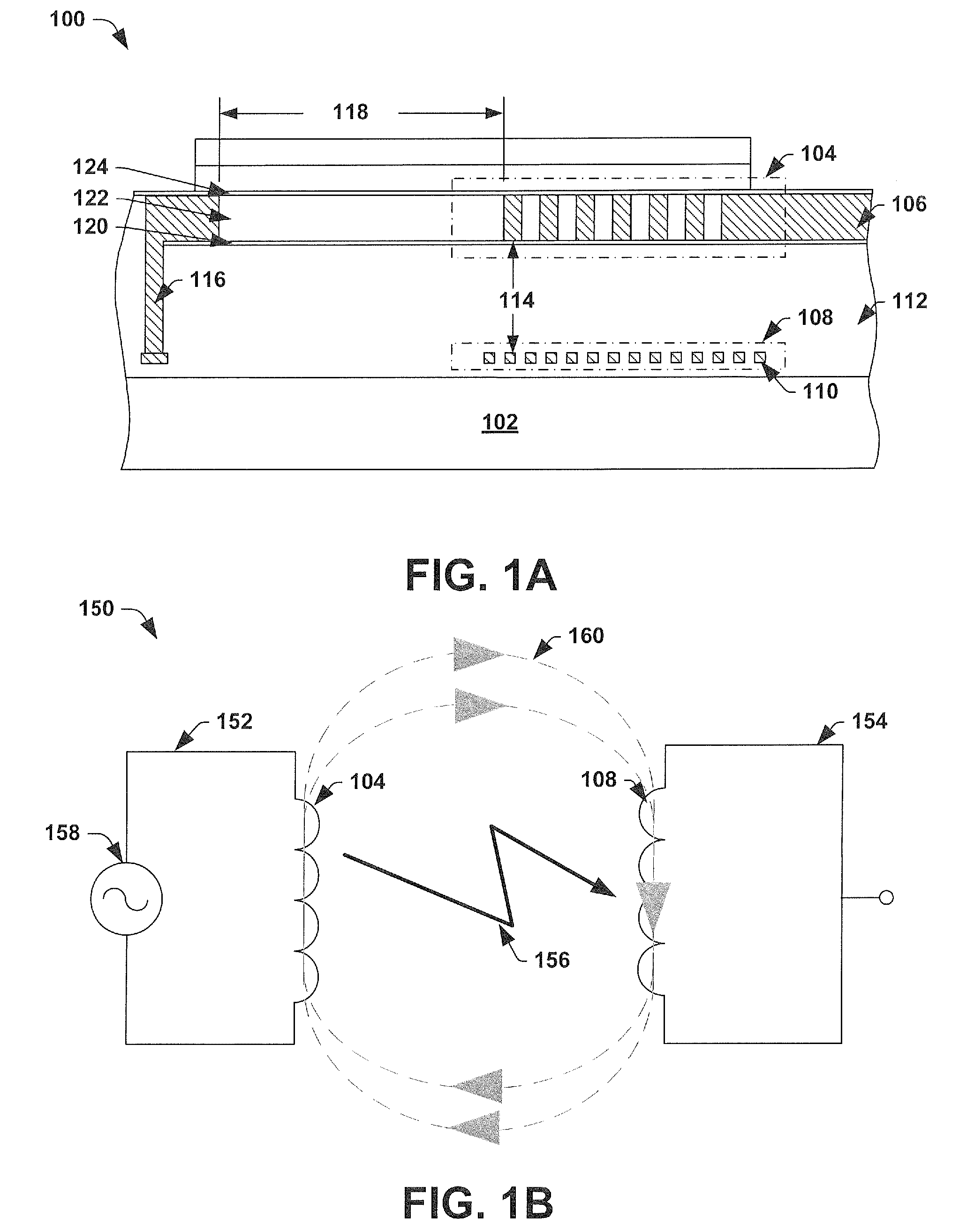
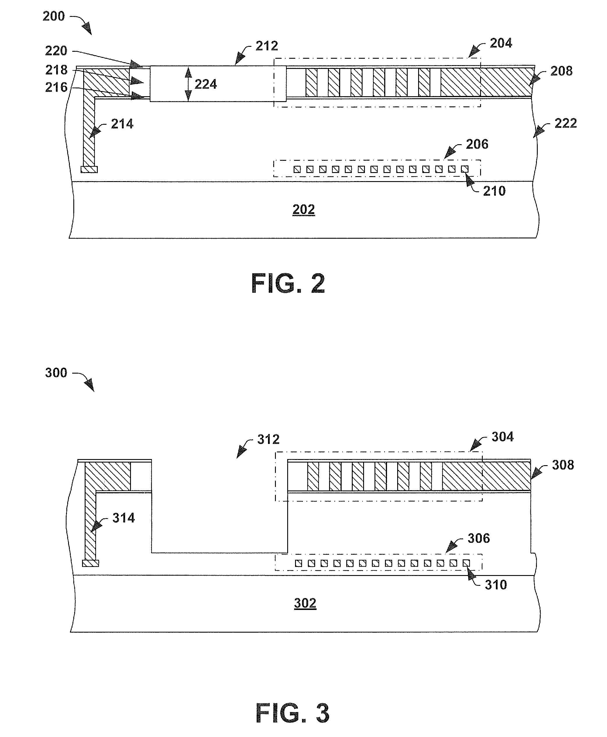
[0015]Electrically isolated circuits have come to be widely used in modern day integrated chips. Often circuits comprised within a common integrated chip need to be electrically isolated to avoid harmful results such as ground loops, noise, temperature variations, etc. As circuits increase in speed and density, couplers are being developed to use a relatively small area while providing fast and accurate data transfer rates between isolated circuits. Magnetic couplers, configured to transfer signals between isolated circuits using a magnetic field, have been shown to be particularly useful in offering these qualities.

[0016]Magnetic couplers comprise one or more conductive elements (e.g., coils) configured to produce a magneti...


PUM


Abstract

The disclosed invention provides a structure and method for providing a high lateral voltage resistance between the electrical networks, sharing a lateral plane, of conductive elements (e.g., having different high voltage potentials) comprising a coupler. In one embodiment, an integrated coupler providing a high lateral voltage resistance comprises a primary conductive element and a secondary conductive element. An isolating material is laterally configured between the electrical network of the primary conductive element and an electrical network of the secondary conductive element. The isolating material may comprise a low-k dielectric layer and prevents any lateral barrier layers (e.g., etch stop layers, diffusion barrier layers, etc.) from extending between the first conductive element and the electrical network of the second conductive element. The structure therefore provides a galvanically isolated integrated coupler which avoids electrical shorting between circuits (e.g., at barrier layers) resulting in an improved high voltage resistance.

Description

FIELD OF INVENTION[0001]The present invention relates generally to integrated circuit isolation and in particular to a method and apparatus by which continuous barrier layers, located between conductive structures in an integrated chip, can be avoided.BACKGROUND OF THE INVENTION[0002]In many modern day circuit configurations, there is a need for electrical or galvanic isolation between different sections of the circuit. Galvanic isolation is often used where a potential voltage difference exists between circuits having different ground domains. If the circuits are not isolated, unwanted current can flow in the circuits (e.g., a ground loop current) leading to noise, signal degradation, circuit damage, or even electrical shock.[0003]However, often the two or more electrically isolated circuits need to communicate for proper operation of a system. Couplers may be used to facilitate such communication. Couplers allow signals (e.g., information, energy) to be transferred between such el...

Claims


Application Information

Patent Timeline
IPC IPC(8): H01L29/06H01L21/762
CPCH01L23/5227H01L2224/02166H01L23/642H01L23/585H01L2924/14H01L24/05H01L2924/01029H01L2924/13091H01L23/3178H01L24/03H01L2224/03462H01L2224/03464H01L2224/05155H01L2224/05644H01L2924/01015
Inventor WAHL, UWEHAMMER, MARKUSSTENGL, JENS-PEER
Owner INFINEON TECH AUSTRIA AG
Why Eureka
Try Eureka