Electric apparatus module

a technology of electrical apparatus and module, which is applied in the direction of electrical apparatus casing/cabinet/drawer, electrical apparatus construction details, coupling device connections, etc., can solve the problems of interference in normal operation, and achieve the effect of suppressing the number of assembling processes, good shielding efficiency, and increasing the number of components

Active Publication Date: 2011-04-28
YAZAKI CORP
View PDF7 Cites 26 Cited by
  • Summary
  • Abstract
  • Description
  • Claims
  • Application Information

AI Technical Summary

Benefits of technology

[0021]As explained above, according to the first aspect of the invention, since the shield shell covering the electronic device unit is made directly in contact with the ground shell to thereby directly contact the ground shell to the shield member of the connector to thereby couple to the attached member, noise entering into the electronic device unit from the outside can be released to the attached member via the shield shell, the shield member and the ground shell without passing through an electric circuit coupled to the electronic device unit. Thus, the entering of noise can be surely prevented and so good shielding efficiency can be attained. Further, since the shield shell and the shield member of the connector can be coupled to the attached member via the ground shell, the increase of the number of components and the number of assembling processes can be suppressed. Thus, the assembling procedure can be performed easily.
[0022]According to the second aspect of the invention, since the contact piece of the ground shell can be easily and surely made in contact with the shield shell, the shield shell can be surely coupled to the attached member via the ground shell and the coupling procedure between the shield shell and the ground shell can be simplified. As a result, noise entering into the electronic device unit from the outside can be surely released to the attached member via the shield shell and the ground shell. Further, the number of the processes for assembling the shield shell and the ground shell can beg suppressed.
[0023]According to the third aspect of the invention, a plurality of the contact portions are provided between the shield shell and the ground shell and the contact portions are disposed around the electronic device unit. Thus, since the shield shell and the ground shell can be directly made in contact to each other surely, the shield shell can be surely coupled to the attached member via the ground shell. As a result, noise entering into the electronic device unit from the outside can be surely released to the attached member via the shield shell and the ground shell.
[0024]According to the fourth aspect of the invention, since the ground shell can be made in contact with the shield member of the connector by inserting the contact member into the shield member, the ground shell can be easily and surely made in contact with the shield member of the connector. Thus, the shield member of the connector can be easily coupled to the attached member via the ground shell and the coupling procedure between the shield member of the connector and the ground shell can be simplified. As a result, noise entering into the electronic device unit from the outside can be surely released to the attached member via the shield member of the connector and the ground shell. Further, the number of the processes for assembling the shield member of the connector and the ground shell can beg suppressed.

Problems solved by technology

In this case, since a signal transmitted between the aforesaid camera module and the monitor is a digital signal, the signal is likely influenced by noise and so a normal operation may be interfered.

Method used


Image

  • Electric apparatus module
  • Electric apparatus module
  • Electric apparatus module

Examples


embodiment 1

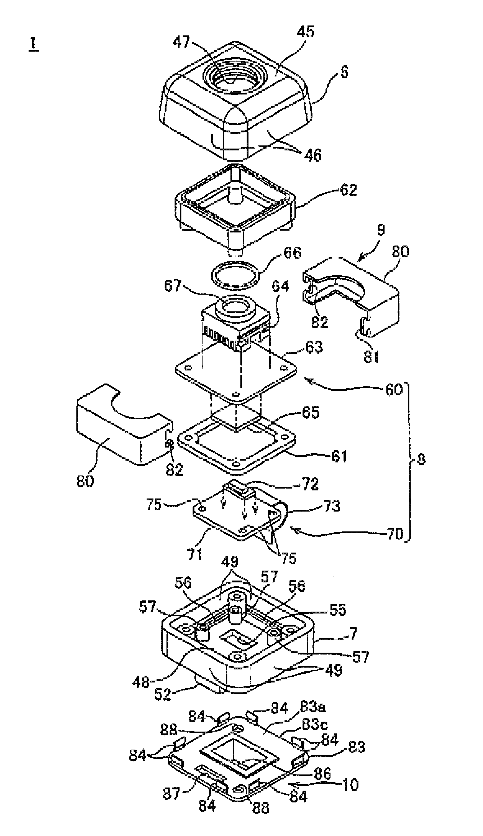
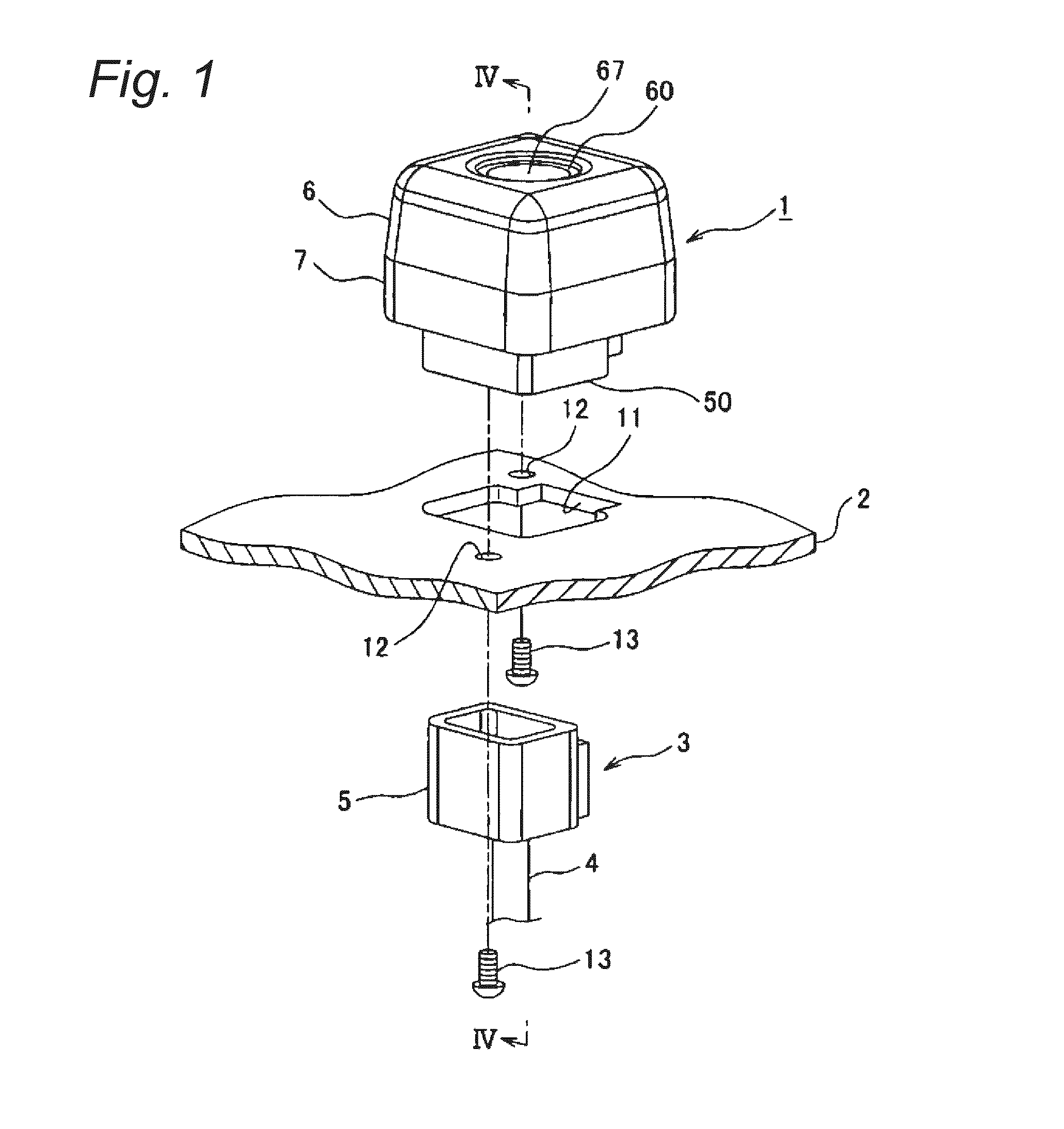
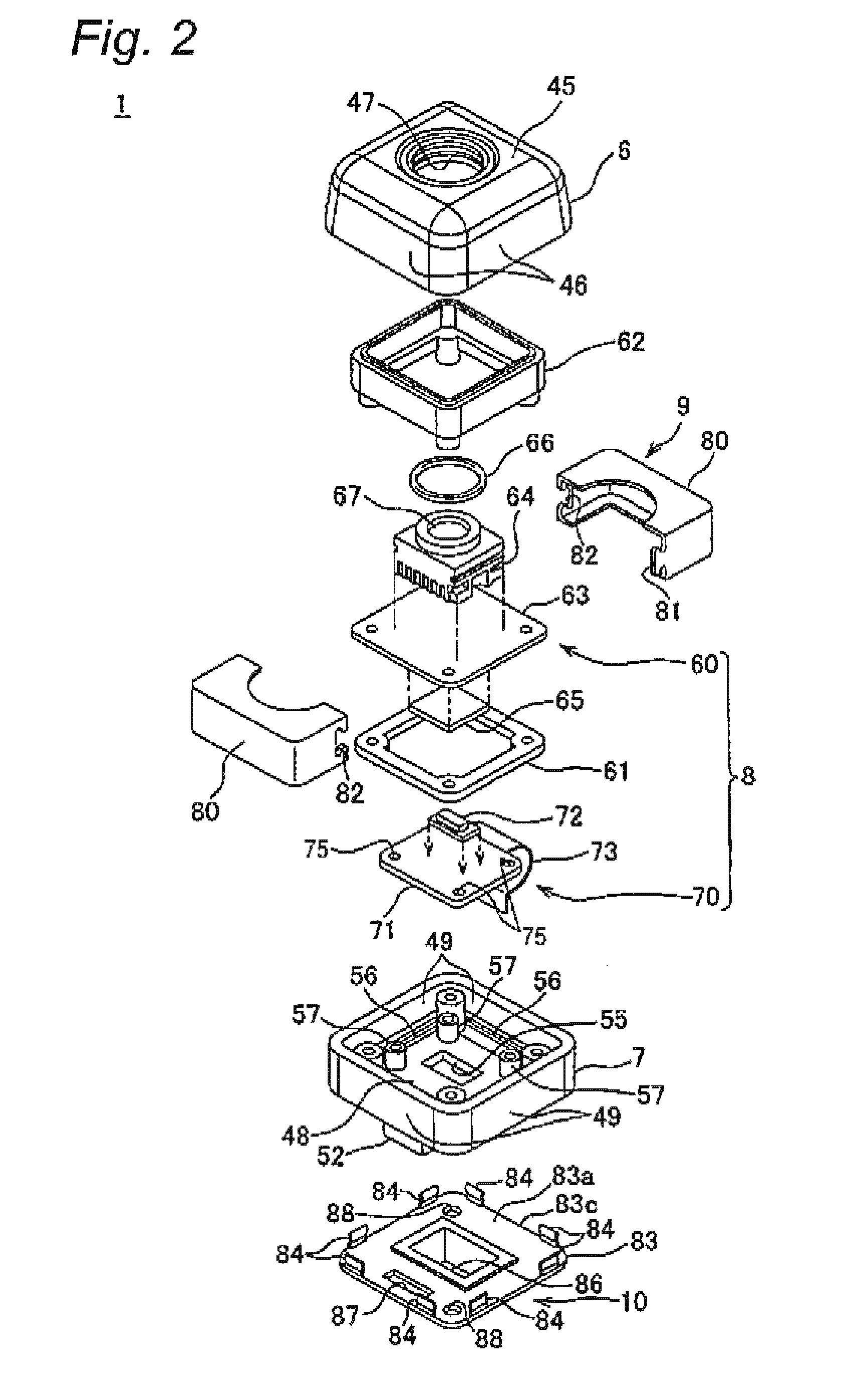
[0031]An electric apparatus module according to an embodiment of the invention will be explained with reference to FIGS. 1 to 5. The electric apparatus module 1 shown in FIG. 1 etc. is attached to the upper portion of the rear side of an automobile (for example, the upper portion of a rear panel 2) etc.

[0032]The rear panel 2 is a part of the body of an automobile and configured by a sheet metal etc. As shown in FIG. 1, the rear panel 2 is provided with a hole 11 for passing a connector 5 provided at the end portion of a wire harness 3 wired within the automobile and holes 12 for passing screws 13. The wire harness 3 is coupled to a monitor (not shown) as an external device to be attached to the instrument panel of the automobile.

[0033]The wire harness 3 includes a shield harness 4 and the connector 5 to be attached to the end portion of the shield harness 4. The connector 5 corresponds to the connector of the external device described in claims. The shield harness 4 includes a plura...


PUM


Abstract

An electric apparatus module 1 includes an upper casing 6, a lower casing 7 to which the upper casing 6 is attached and which is attached to a rear panel 2, an electronic device unit 8 accommodated in the upper casing 6 and the lower casing 7, a conductive shield shell 9 covering the electronic device unit 8, and a conductive ground shell 10 which is attached to the lower casing 7 at a side of the rear panel 2. The ground shell 10 includes a flat plate portion 83 piled on the rear panel 2, a contact piece 84 erected from an outer edge 83c of the flat plate portion 83 toward the lower case 7, and a contact member 85 protruded from a rear surface 83b of the flat plate portion 83 at the side of the rear panel 2. The contact piece 84 is inserted through a through hole 56 formed on the lower casing 7 to contact with the shield shell 9. The contact member 85 is inserted through a through hole 11 formed on the rear panel 2 to contact a cylindrical shield member 22 of an external device.

Description

TECHNICAL FIELD[0001]The present invention relates to an electric apparatus module which is configured by housing, within a casing, a camera module as an electronic device unit to be attached to a predetermined position such as the upper portion of the rear side of an automobile, for example.BACKGROUND TECHNIQUE[0002]There is a case that an electric apparatus module is mounted which is configured by housing, within a casing, a camera module as an electronic device unit to be attached to a predetermined position such as the upper portion of the rear side of an automobile as movable body. The electric apparatus module includes an upper casing, a lower casing to which the upper casing is attached and which is attached to the panel of an automobile as a subject member to which the upper casing is attached, a camera module as the electronic device unit which is housed between the upper casing and the lower casing, and a coupling unit for coupling the camera module with an external device...

Claims


Application Information

Patent Timeline
Patent Type & Authority Applications(United States)
IPC IPC(8): H05K9/00
CPCH01R13/506H01R2201/26H01R13/74H01R13/65802H01R13/6582
Inventor KAMEYAMA, ISAO
Owner YAZAKI CORP
Why Eureka
Try Eureka