Packet mode auto-detection in multi-mode wireless communication system, signal field transmission for the packet mode auto-detection, and gain control based on the packet mode

a multi-mode wireless communication system and packet mode technology, applied in wireless commuication services, data switching networks, phase-modulated carrier systems, etc., can solve the problems of high probability, low reliability of conventional packet mode detection methods, and large difficulty in discriminating ht signal fields and 64-qam modulation signals. achieve the effect of high reliability

Active Publication Date: 2011-04-28
ELECTRONICS & TELECOMM RES INST
View PDF7 Cites 89 Cited by
  • Summary
  • Abstract
  • Description
  • Claims
  • Application Information

AI Technical Summary

Benefits of technology

[0014]An embodiment of the present invention is directed to a method for automatically detecting a packet mode in a wireless communication system supporting multi-mode packets, which can perform an automatic packet mode detection with a high reliability while providing a compatibility with the conventional method.
[0015]Another embodiment of the present invention is directed to a method for automatically detecting a packet mode in a multi-mode wireless communication system with a high reliability by using a data rate value and a packet length setting value.
[0016]Another embodiment of the present invention is directed to a method for transmitting a signal field in a multi-mode wireless communication system by using a modulation scheme based on the phase rotation of a data tone and / or a pilot tone, which can implement an automatic packet mode detection with a high reliability while providing a compatibility with the conventional method.
[0018]Another embodiment of the present invention is directed to a method for automatically detecting a packet mode in a multi-mode wireless communication system by using a reserved bit of a signal field L-SIG for a legacy terminal and a reserved bit of a signal field HT-SIG for an HT terminal, which can perform an automatic packet mode detection with a high reliability while providing a compatibility with the conventional method.

Problems solved by technology

However, such a conventional packet mode detection method has a great difficulty in discriminating a Q-BPSK modulation signal of an HT signal field and a 64-QAM modulation signal for data.
First, the conventional method is low in terms of the reliability of packet mode detection. The method of discriminating between a 64-QAM signal and a Q-BPK signal by a detection threshold value as illustrated in FIG. 1 is low in terms of a signal-to-noise ratio (SNR) and has a high probability that a mode detection error may occur due to a noise in a poor environment with a severe channel change. A 64-QAM signal is the maximum modulation mode in the conventional method, but the problem becomes more serious if the higher modulation scheme (e.g., a 256-QAM modulation scheme) is used for a very, high throughput mode. Therefore, a simple comparison of BPSK and Q-BPSK can be made according to the 6 Mbps data rate setting of a legacy signal field, but it is difficult to detect an error in the legacy signal field through a one-bit parity check if channel environment is poor.
Secondly, the conventional method is low in terms of extendibility. If the conventional method is used to discriminate between an HT mode and a Very High Throughput (VHT) mode (the mode following the HT mode) in the HT-SIG, an automatic packet mode detection becomes impossible because the I energy and the Q energy become equal in the case of a terminal using both of the two HT-SIG symbols among the terminals supporting the IEEE 802.11n standards. Accordingly, the total network throughput decreases and the power consumption efficiency decreases.
The above problems of the conventional method may become more serious when detecting packets based on the Very High Throughput (VHT) wireless communication standards (e.g., IEEE 802.11ac) following the conventional wireless LAN standards.

Method used


Image

  • Packet mode auto-detection in multi-mode wireless communication system, signal field transmission for the packet mode auto-detection, and gain control based on the packet mode
  • Packet mode auto-detection in multi-mode wireless communication system, signal field transmission for the packet mode auto-detection, and gain control based on the packet mode
  • Packet mode auto-detection in multi-mode wireless communication system, signal field transmission for the packet mode auto-detection, and gain control based on the packet mode

Examples


Embodiment Construction

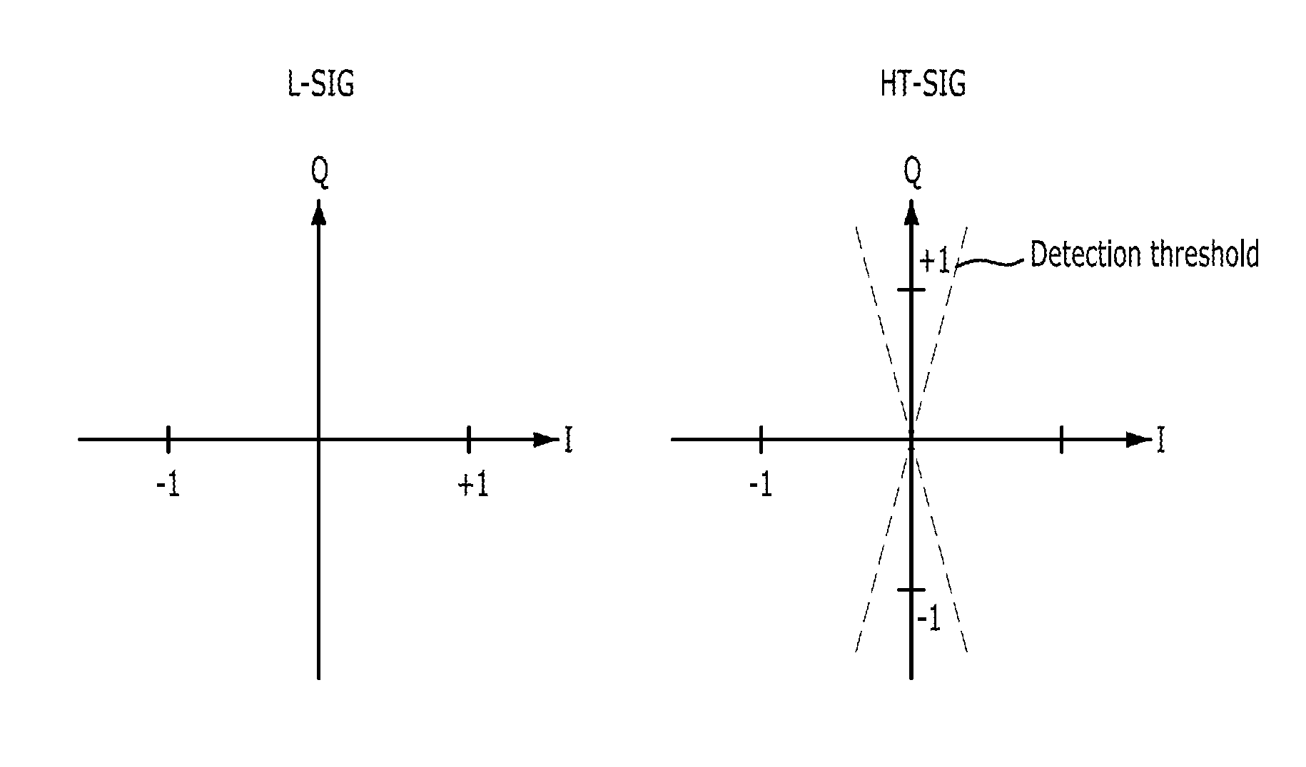
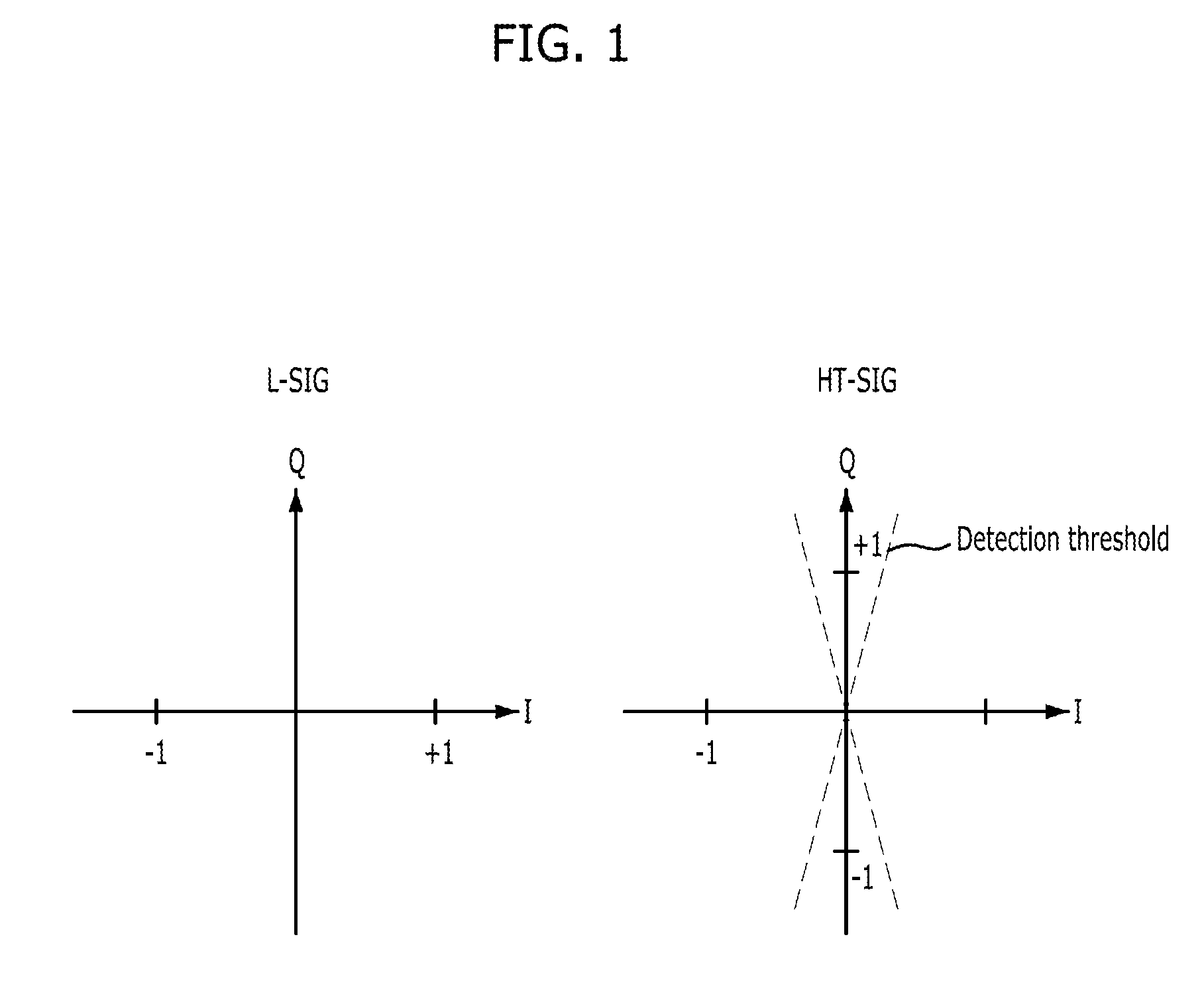
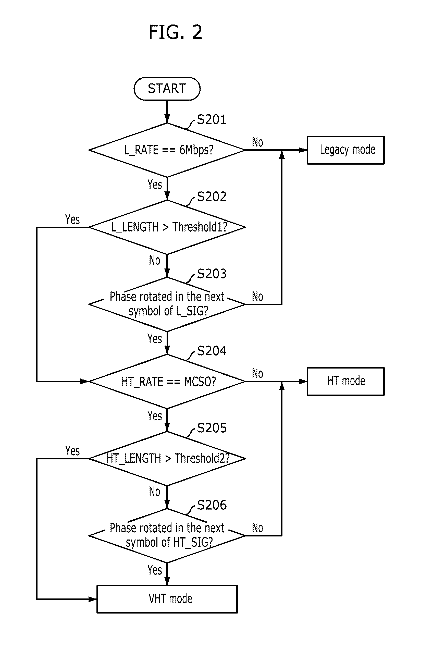
[0059]Exemplary embodiments of the present invention will be described below in more detail with reference to the accompanying drawings. The present invention may, however, be embodied in different forms and should not be constructed as limited to the embodiments set forth herein. Rather, these embodiments are provided so that this disclosure will be thorough and complete, and will fully convey the scope of the present invention to those skilled in the art. Throughout the disclosure, like reference numerals refer to like parts throughout the various figures and embodiments of the present invention.

[0060]The foregoing objects and advantages of the present invention will be described below in detail with reference to the accompanying drawings so that the technical concept of the present invention can be easily realized by those skilled in the art to which the present invention pertains. In the following description, detailed descriptions of well-known functions or configurations will ...


PUM


Abstract

A method for automatically detecting a packet mode in a wireless communication system supporting a multiple transmission mode includes: acquiring at least one of data rate information, packet length information and channel bandwidth information from a transmitted frame; and determining the packet mode on the basis of the phase rotation check result of a symbol transmitted after a signal field signal and at least one of the data rate information, the packet length information and the channel bandwidth information acquired from the transmitted frame.

Description

CROSS-REFERENCE(S) TO RELATED APPLICATIONS[0001]The present application claims priority of Korean Patent Application No(s). 10-2009-0101925 (and 10-2009-0101956, 10-2010-0006218, 10-2010-0013642), filed on Oct. 26, 2009, (and Oct. 26, 2009, Jan. 22, 2010, Feb. 12, 2010, respectively,) which is (are) incorporated herein by reference in its (their) entirety.BACKGROUND OF THE INVENTION[0002]1. Field of the Invention[0003]Exemplary embodiments of the present invention relate to packet mode auto-detection in a multi-mode wireless communication system, signal field transmission for the packet mode auto-detection, and gain control based on the packet mode; and, more particularly, to a method for automatically detecting a packet mode in a multi-mode wireless communication system (e.g., a Wireless Local Area Network (WLAN) communication system supporting various modes) by using a data rate value and a packet length setting value, a method for transmitting a signal field for auto-detection of...

Claims


Application Information

Patent Timeline
Patent Type & Authority Applications(United States)
IPC IPC(8): H04L12/26H04W4/00
CPCH04L27/0012H04W72/042H04L27/22H04L27/2003H04L27/2601H04L43/08H04W28/02H04L65/00H04W72/23H04L5/0048H04L27/2273H04L27/3444H04W84/12
Inventor LEE, IL-GUCHOI, EUN-YOUNGLEE, SOK-KYU
Owner ELECTRONICS & TELECOMM RES INST
Why Eureka
Try Eureka