Diaphragm, method making the same and loudspeaker using the same

a diaphragm and diaphragm technology, applied in the direction of transducer diaphragms, mechanical vibration separation, paper/cardboard containers, etc., can solve problems such as audible distortion

Active Publication Date: 2011-04-28
TSINGHUA UNIV +1
View PDF42 Cites 16 Cited by
  • Summary
  • Abstract
  • Description
  • Claims
  • Application Information

AI Technical Summary

Problems solved by technology

However, when the input power is increased to certain levels, the ...

Method used


Image

  • Diaphragm, method making the same and loudspeaker using the same
  • Diaphragm, method making the same and loudspeaker using the same
  • Diaphragm, method making the same and loudspeaker using the same

Examples


Embodiment Construction

[0022]The disclosure is illustrated by way of example and not by way of limitation in the figures of the accompanying drawings in which like references indicate similar elements. It should be noted that references to “an” or “one” embodiment in this disclosure are not necessarily to the same embodiment, and such references mean at least one.

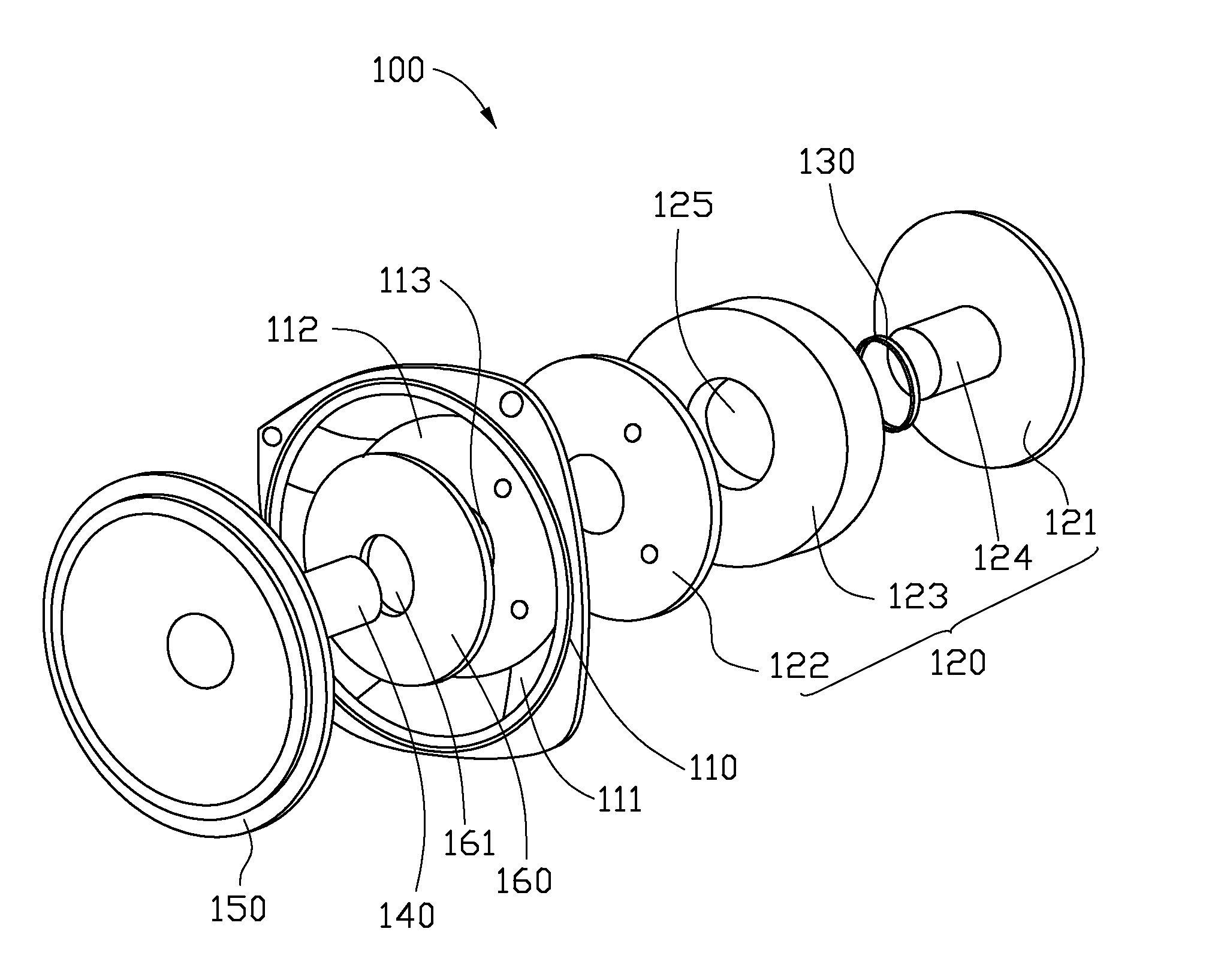
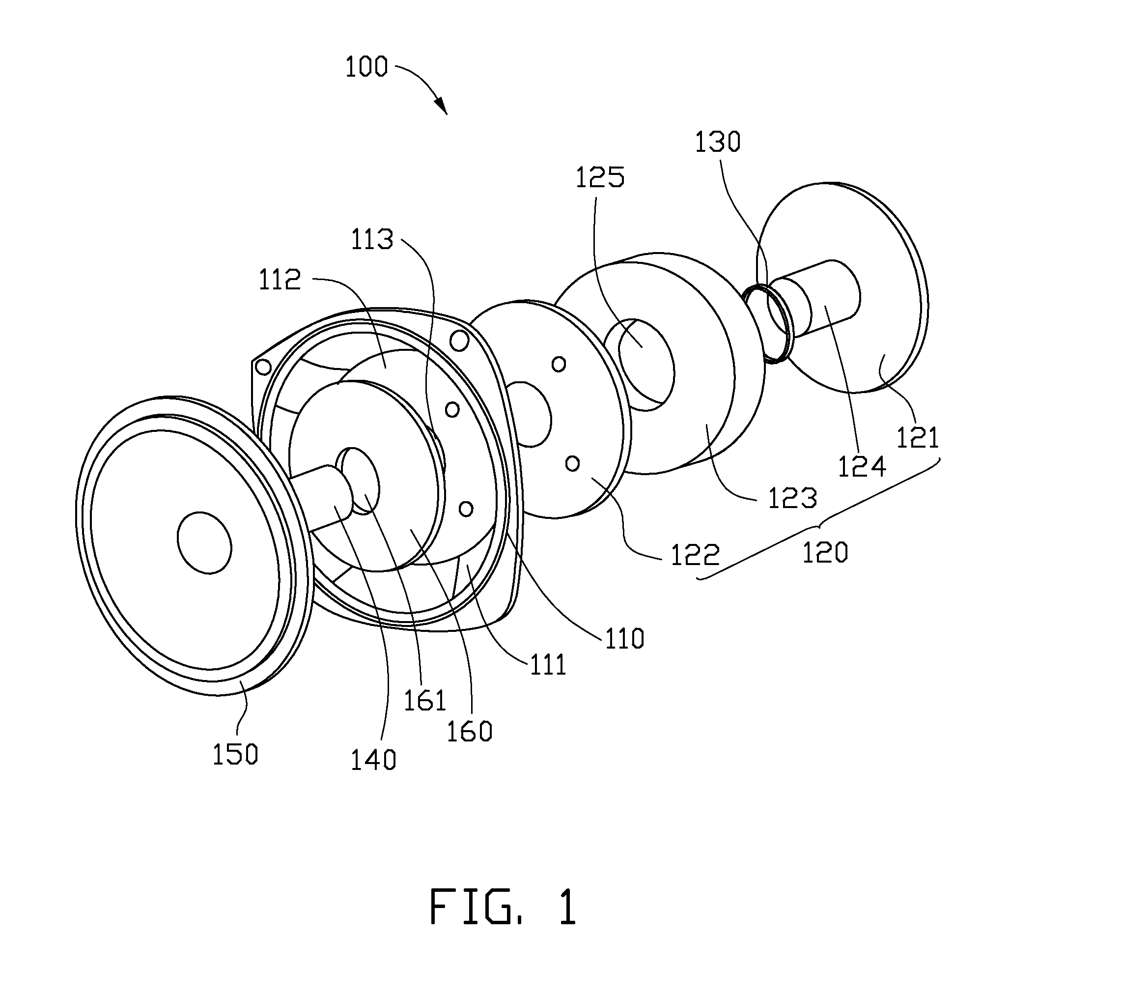
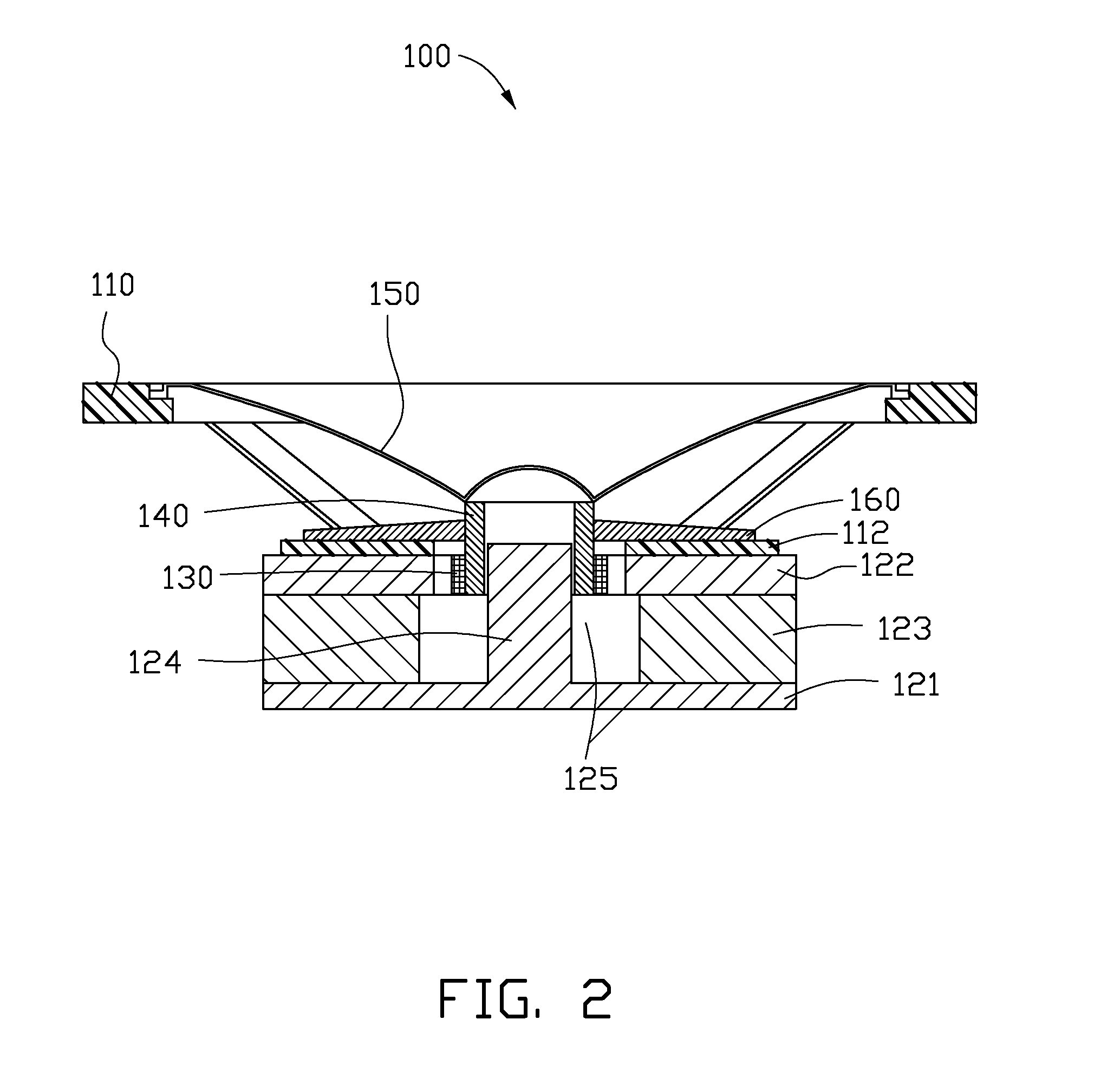
[0023]Referring to FIG. 1 and FIG. 2, one embodiment of a loudspeaker 100 is shown. The loudspeaker 100 includes a frame 110, a magnetic circuit 120, a voice coil 130, a bobbin 140, a diaphragm 150 and a damper 160.

[0024]The frame 110 can be mounted on an upper side of the magnetic circuit 120. The voice coil 130 can be received in the magnetic circuit 120. The voice coil 130 can wind around the voice coil bobbin 140. An outer rim of the diaphragm 150 can be fixed to an inner rim of the frame 110, and an inner rim of the diaphragm 150 can be fixed to an outer rim of the bobbin 140 placed in the magnetic circuit 120.

[0025]The frame 110 can be a tr...


PUM

PropertyMeasurementUnit
Diameteraaaaaaaaaa
Shapeaaaaaaaaaa
Attractive forceaaaaaaaaaa

Abstract

A diaphragm includes a carbon nanotube film structure and an amorphous carbon structure composited with the carbon nanotube structure to form a stratiform composite structure. The carbon nanotube film structure defines a plurality of micropores therein. The amorphous carbon structure comprises a plurality of amorphous carbon particles received in the micropores.

Description

CROSS-REFERENCE TO RELATED APPLICATIONS[0001]This application claims all benefits accruing under 35 U.S.C. §119 from China Patent Application No. 200910110321.6, filed on 2009 Oct. 23, in the China Intellectual Property Office, the disclosure of which is hereby incorporated by reference. This application is related to commonly-assigned applications entitled, “DAMPER AND LOUDSPEAKER USING THE SAME,” filed **** (Atty. Docket No. US27614), and “BOBBIN AND LOUDSPEAKER USING THE SAME,” filed **** (Atty. Docket No. US27613).BACKGROUND[0002]1. Technical Field[0003]The present disclosure relates to a diaphragm, a method making the same, and a loudspeaker using the same.[0004]2. Description of Related Art[0005]An electro-dynamic loudspeaker typically includes a diaphragm, a bobbin, a voice coil, a damper, a magnet, and a frame. The voice coil is an electrical conductor and is placed in the magnetic field of the magnet. By applying an electric signal to the voice coil, a mechanical vibration ...

Claims


Application Information

Patent Timeline
IPC IPC(8): H04R7/00H04R1/02B05D3/02
CPCH04R7/125Y10T428/13H04R2307/023H04R31/003C01B32/162H01B1/04Y10T428/249978B32B1/08B32B5/02B32B5/16B82B3/0047B82Y10/00B82Y30/00B82Y40/00H04R1/025H04R5/02H04R9/046H04R13/02H04R23/002
Inventor WANG, JIA-PINGLIU, LIANG
Owner TSINGHUA UNIV
Why Eureka
Try Eureka