

Pump control device, oil well with device and method
a technology of control device and oil well, which is applied in the direction of pump control, positive displacement liquid engine, machine/engine, etc., can solve the problems of controlling device for oil well operation and oil well using our control devi
- Summary
- Abstract
- Description
- Claims
- Application Information
AI Technical Summary
Benefits of technology
Problems solved by technology
Method used
Image

Examples
Embodiment Construction
.” The claims that follow define our method and control device for operating an oil well, and an oil well using our control device, distinguishing them from the prior art; however, without limiting the scope of our method and control device for operating an oil well, and an oil well using our control device, as expressed by these claims in general terms, some, but not necessarily all, of their features are:
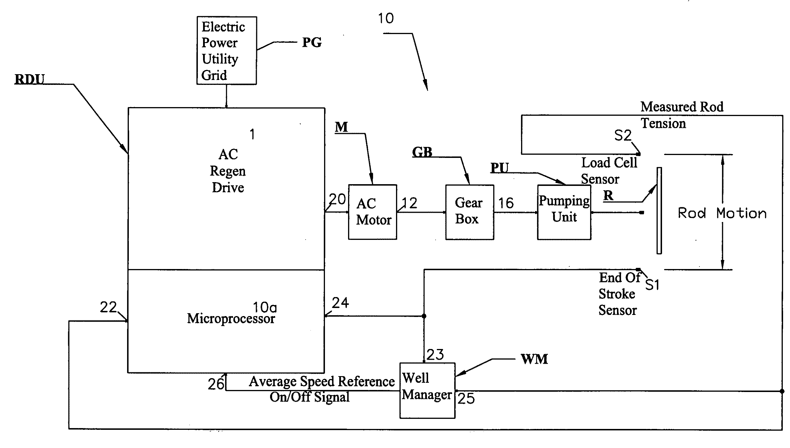
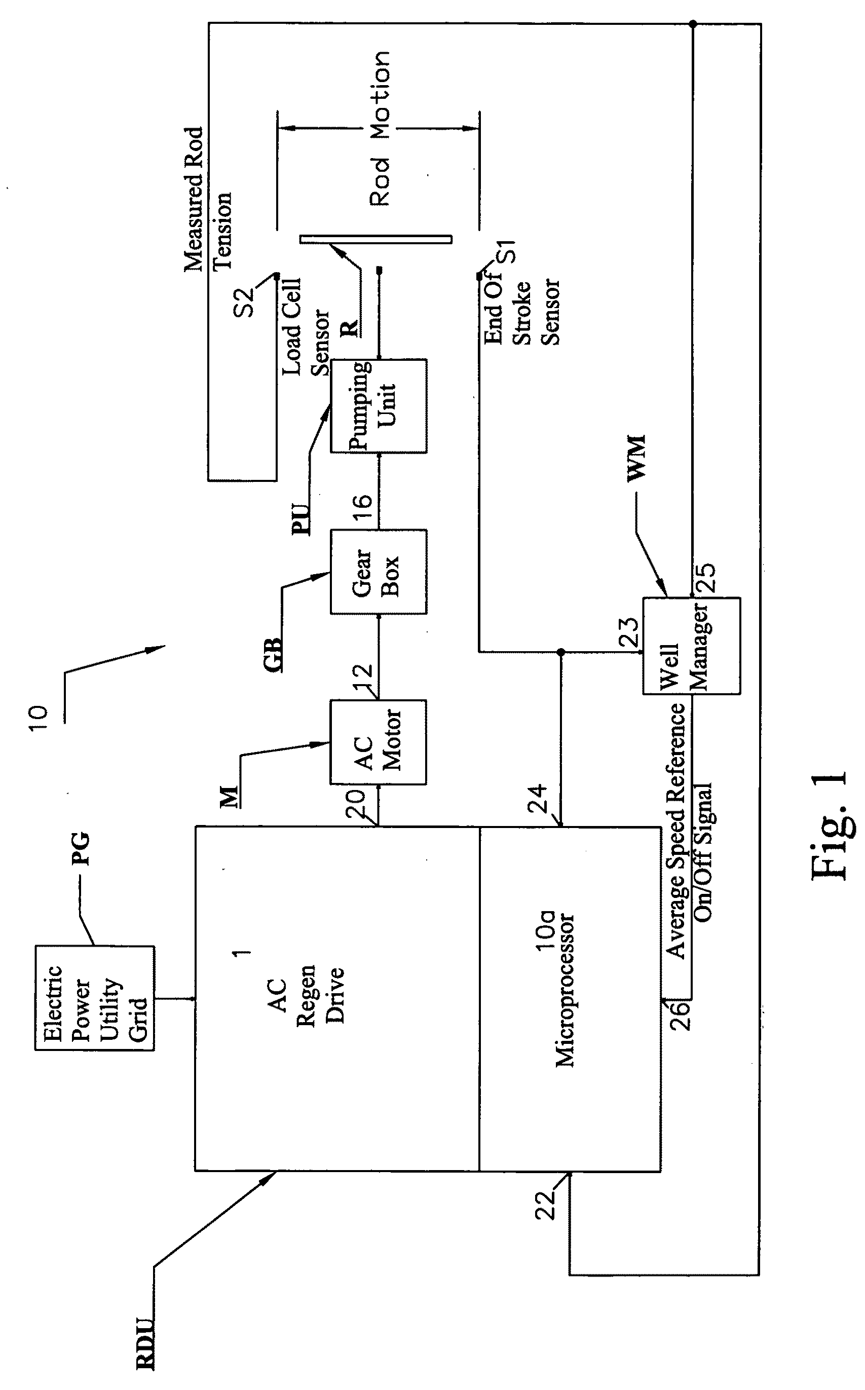
[0007]One, our oil well includes a pump having a drive mechanism operably connected to an AC electric motor powered by AC electrical energy from a power grid, and a variable frequency AC drive that controls the AC electrical energy applied to the motor to decrease motor speed by transferring the electrical energy to the power grid and to increase motor speed by transferring the electrical energy from the power grid to the motor. The variable frequency AC drive is programmed to regulate the motor speed in a manner to optimize oil production and maximize the operational life of the ...
PUM
 Abstract
Description
Claims
Application Information