Perpendicular magnetic recording medium
- Summary
- Abstract
- Description
- Claims
- Application Information
AI Technical Summary
Benefits of technology
Problems solved by technology
Method used
Image

Examples
first embodiment
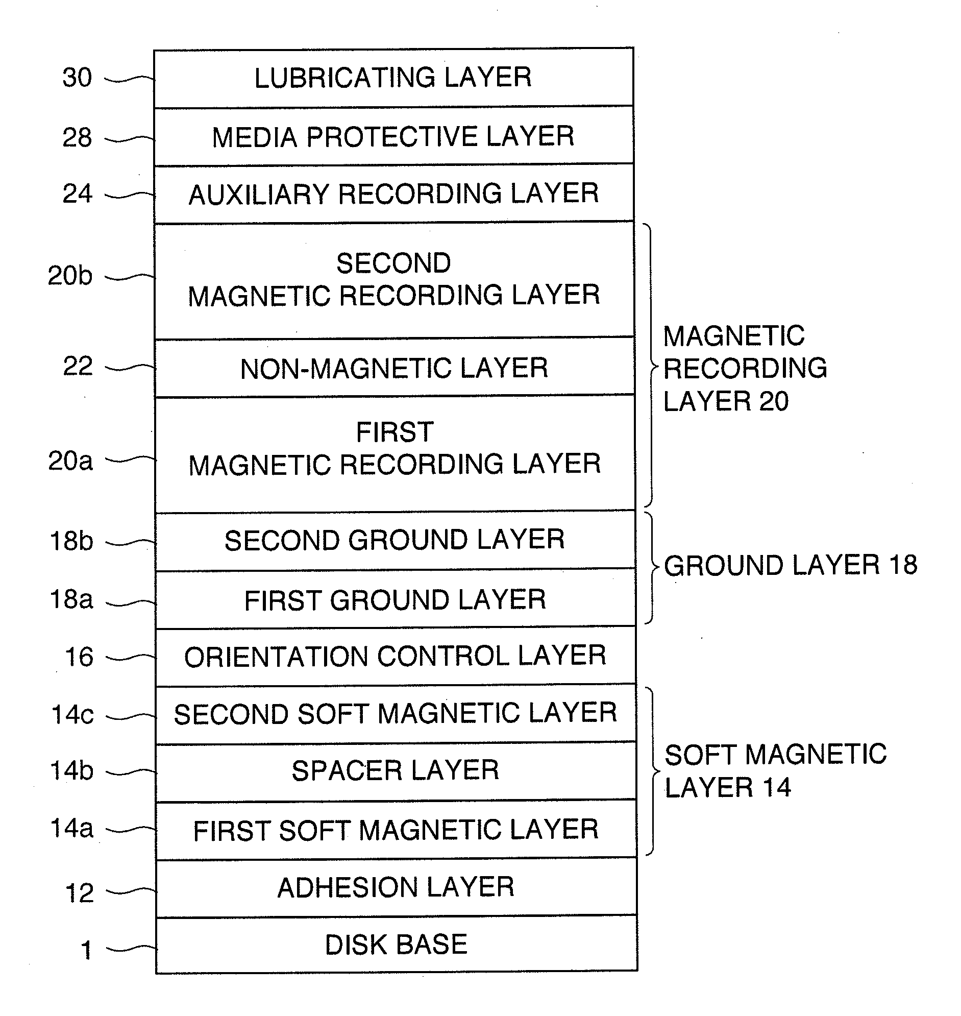
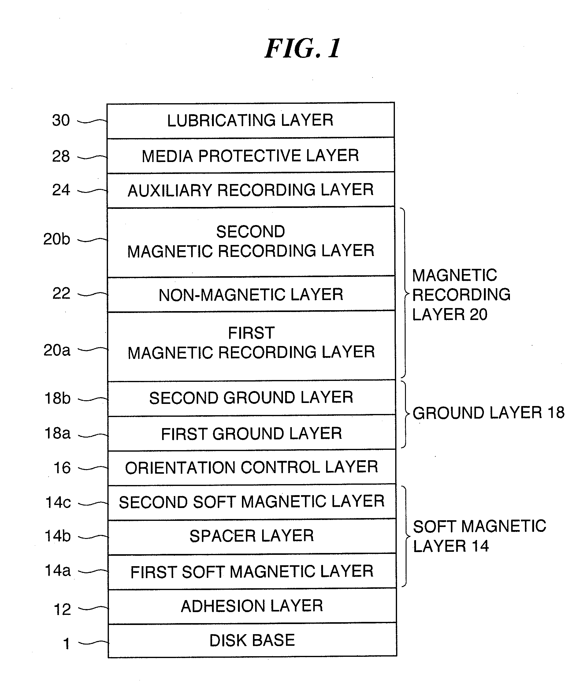
[0031]The magnetic recording medium depicted in FIG. 1 is configured of a disk base 10, an adhesion layer 12, a first soft magnetic layer 14a, a spacer layer 14b, a second soft magnetic layer 14c, a preliminary ground layer 16, a first ground layer 18a, a second ground layer 18b, a first magnetic recording layer 20, a non-magnetic layer 22, a second magnetic recording layer 20b, an auxiliary recording layer 24, a medium protective layer 28, and a lubricating layer 30 multilayered in this order. Note that the first soft magnetic layer 14a, the spacer layer 14b, and the second soft magnetic layer 14c together form a soft magnetic layer 14. The first ground layer 18a and the second ground layer 18b together form a ground layer 18. The first magnetic recording layer 20a, the non-magnetic layer 22, and the second magnetic recording layer 20b together form a magnetic recording layer 20.
[0032]As the disk base 10, for example, a glass substrate, an aluminum substrate, a silicon substrate, o...
second embodiment
[0062]Next, a second embodiment of the present invention is described. In the first embodiment, the second magnetic recording layer is configured of one layer. By contrast, in the second embodiment, the second magnetic recording layer is configured of two layers, a first main recording layer and a second main recording layer. Note that the layer provided between the first magnetic recording layer and the second magnetic recording layer is referred to as a non-magnetic layer in the first embodiment, such a non-magnetic layer is referred to as an intervening layer in the second embodiment.
[0063]FIG. 6 is a diagram for describing the configuration of a perpendicular magnetic recording medium 100 according to the second embodiment. The perpendicular magnetic recording medium 100 depicted in FIG. 6 is configured of a disk base 110, an adhesion layer 112, a first soft magnetic layer 114a, a spacer layer 114b, a second soft magnetic layer 114c, a preliminary ground layer 116, a first groun...
examples
[0094]On the disk base 110, by using a vacuumed film forming device, the adhesion layer 112 to the auxiliary recording layer 126 were sequentially formed in an Ar atmosphere by DC magnetron sputtering. The adhesion layer 112 was of CrTi. In the soft magnetic layer 114, the composition of the first soft magnetic layer 114a and the second soft magnetic layer 114c was of CoFeTaZr, and the composition of the spacer layer 114 was of Ru. The composition of the preliminary ground layer 116 was of NiW. As the first ground layer 118a, a Ru film was formed in an Ar atmosphere at a predetermined pressure (low pressure: for example, 0.6 to 0.7 Pa). As the second ground layer 118b, a Ru (RuO) film containing oxygen was formed by using a target including oxygen in an Ar atmosphere at a pressure (high pressure: for example, 4.5 to 7 Pa) higher than a predetermined pressure. In the lower recording layer 122a, Cr2O3 was contained in the grain boundary part as an example of oxide to form an hcp cryst...
PUM
 Abstract
Description
Claims
Application Information
 - Generate Ideas
- Intellectual Property
- Life Sciences
- Materials
- Tech Scout
- Unparalleled Data Quality
- Higher Quality Content
- 60% Fewer Hallucinations
Browse by: Latest US Patents, China's latest patents, Technical Efficacy Thesaurus, Application Domain, Technology Topic, Popular Technical Reports.
© 2025 PatSnap. All rights reserved.Legal|Privacy policy|Modern Slavery Act Transparency Statement|Sitemap|About US| Contact US: help@patsnap.com