Automatic registration of images for image guided surgery

a technology of image guided surgery and automatic registration, applied in the field of automatic registration of images for image guided surgery, can solve the problems of low probability of error leading to incorrect patient care, incorrect co-ordinate transformation, and inability to accurately identify the image, and achieve the effect of robust automatic marker recognition

Inactive Publication Date: 2011-04-28
IMRIS
View PDF13 Cites 195 Cited by
  • Summary
  • Abstract
  • Description
  • Claims
  • Application Information

AI Technical Summary

Benefits of technology

[0091]The second kind of automatic registration uses a number of attachable fiducial markers (using adhesive, screw into bone, or the like) that can each be detected in the MR/CT and by the tracking system. Using marker recognition, the system can perform automatic registration. Additionally, the system may opt to include a spacer not visible in imaging to ensure that the MR/CT marker is located away from the skin during imaging; this helps make the automatic marker recognition more robust. The algorithm for this implementation of automatic registration works with an arbitrary arrangement of such markers. This kind of auto registration does not require the

Problems solved by technology

Automating the procedure also reduces the possibility of error, which could lead to incorrect co-ordinate transformations.
Incorrect co-ordinate transformations are typically detected by the image guidance system so the likelihood of an error leading to incorrect patient care is low, but the staff are then required to repeat the manual registration procedure a second time, which further adds to the time the patient is under general anaesthesia.
This arrangement has the disadvantages that it is inherently inaccurate from the fusion process since the pre-op and intra-op images typically have differences in them (moved tissue, etc).
Also, any error from the first registration with the pre-op images is added to with the second registration, creating a larger overall error.
This arrangement has the disadvantages that the anterior coil can move after it has been placed around the patient due to a number of sources including imperfect fit, and this can create large registration errors.
Since the frame is attached to the coil, it needs to be a relatively small size which gives larger errors on average than a larger frame.
Because the long distance to the tracking volume, small errors in the localization of the magnet markers are amplified to large errors in the tracking volume
These devices typically use infra-red or other non-visible optical tracking technolog

Method used


Image

  • Automatic registration of images for image guided surgery
  • Automatic registration of images for image guided surgery
  • Automatic registration of images for image guided surgery

Examples


Embodiment Construction

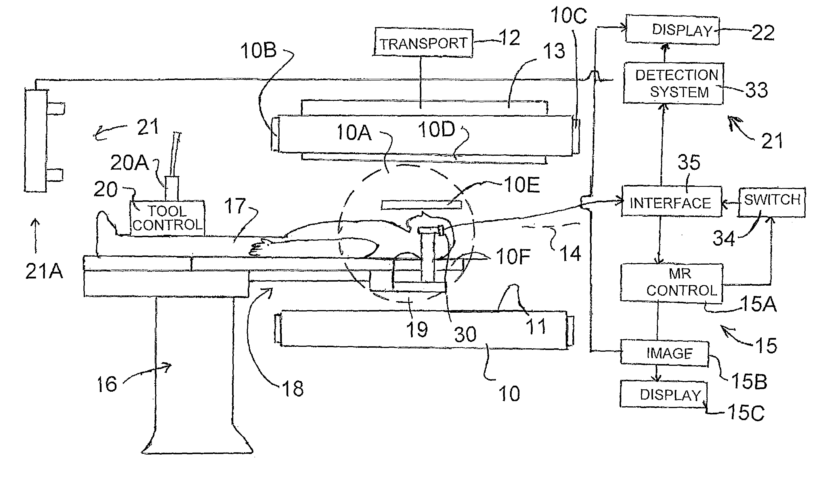
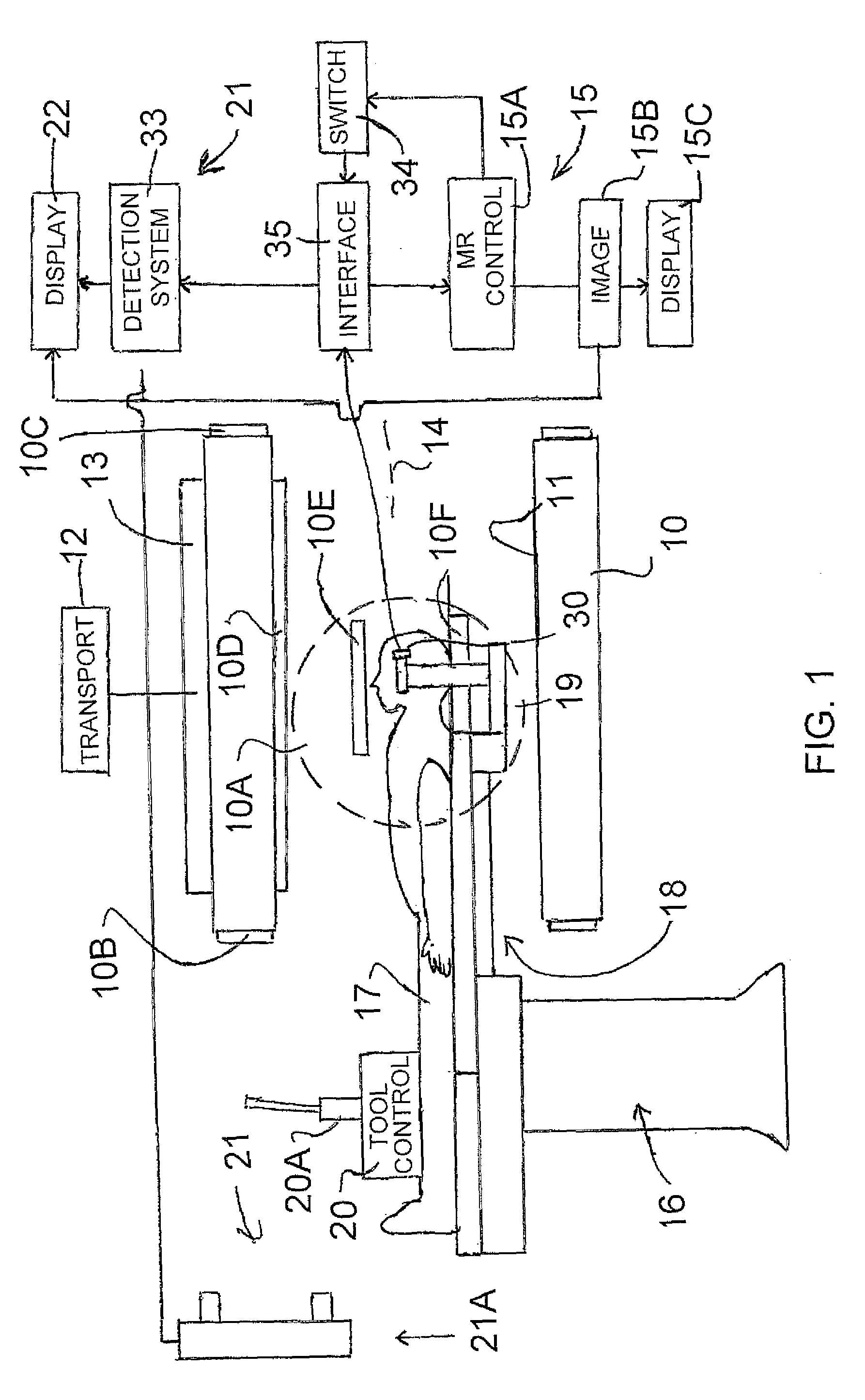
[0129]In FIG. 1 is shown an intra-operative magnetic resonance imagining system of the type shown in U.S. Pat. No. 5,735,278 (Hoult) filed Mar. 15, 1996, the disclosure of which is incorporated herein by reference.

[0130]This system includes a magnetic resonance imagining component which includes a magnet 10 of the type including a generally cylindrical body defining a horizontal bore 11 where the magnet is carried on a track 12 on a suitable mounting assembly 13 allowing the magnet to be moved longitudinally along its axis 14. The remainder of the imaging system is shown schematically at 15 and the details of suitable magnetic resonance imagining systems are of course well known to a person skilled in the art so that no description is necessary here.

[0131]A patient operating table is indicated at 16 on which a patient 17 can be placed for the various procedures. The table is arranged so that it can enter the bore as the front end 18 of the magnet is moved longitudinally along the ax...


PUM


Abstract

Automatic registration of an MR image is carried out in an image guidance system by placing MR visible markers at known positions relative to markers visible in a camera tracking system. The markers are carried on a common fixture which is attached to a head clamp together with a reference marker which is used when the markers are covered or removed. The tracking system includes a camera with a detection array for detecting visible light a processor arranged to analyze the output from the array. Each object to be detected carries a single marker with a pattern of contrasted areas of light and dark intersecting at a specific single feature point thereon with an array around the specific location to allow the processor is able to detect an angle of rotation of the pattern and to distinguish each marker from the other markers.

Description

[0001]This application claims the benefit of Priority under 35 USC 119 from Provisional Application 61 / 255,735 filed Oct. 28, 2009.[0002]This invention relates to a method of registration of an image of a body part of the patient obtained in an imaging system to a position of the patient in a tracking system used in image guided surgery. The imaging system with which the techniques shown herein are to be used is preferably MRI but other systems including particularly CT imaging are also applicable.[0003]This application is related to copending U.S. application Ser. No. 12 / 907,398 filed Oct. 19, 2010 which claims priority from Provisional Application 61 / 253,330 filed Oct. 20, 2009, the disclosures of which are incorporated herein by reference.BACKGROUND OF THE INVENTION[0004]Physicians using an image guidance system during surgery need to relate locations of the patient's anatomy to the image data. This is done via a process called registration and usually, in a manual process, invol...

Claims


Application Information

Patent Timeline
IPC IPC(8): A61B5/055
CPCA61B5/055A61B19/5225A61B2019/5483A61B2019/5236A61B19/5244A61B34/20A61B90/37A61B2090/374A61B2090/3983
Inventor ROBBINS, STEVENSCARTH, GORDONBEN-LAVI, AZISCHAERER, SHAWNBALAKRISHNAN, NISHANT
Owner IMRIS
Why Eureka
Try Eureka