Low friction edge roll to minimize force cycling

a technology of low friction and edge roll, which is applied in the direction of glass rolling apparatus, glass tempering apparatus, manufacturing tools, etc., can solve the problems of unoptimized cooling of the ribbon, undesirable stress and warpage in the final product, and force cycling, so as to reduce the cyclic force, and eliminate the effect of friction

Inactive Publication Date: 2011-05-05
CORNING INC
View PDF22 Cites 13 Cited by
  • Summary
  • Abstract
  • Description
  • Claims
  • Application Information

AI Technical Summary

Benefits of technology

[0004]An apparatus is disclosed for drawing a glass ribbon, and in particular an apparatus having reduced cyclic forces resulting from friction in the drawing apparatus that can manifest as shape or stress within glass sheets cut from the ribbon. A reduction in such force cycling can be achieved by eliminating friction that occurs between moving parts of assemblies that contact the glass ribbon, particularly during the time the glass ribbon is transitioning from a visco-elastic state to an elastic state. This region, known as the setting temperature range, is a temperature range over which the glass has reached a viscosity that stress imparted to the glass can be frozen into the glass. Also disclosed is a method by which a glass ribbon can be drawn from the apparatus.

Problems solved by technology

Frictional forces that resist the free motion of the edge rollers may induce force cycling that manifests as undesirable perturbations or stress changes in the ribbon that can become frozen into the glass as the glass transitions from a viscous material to an elastic material.
An inadequate seal where the shaft of each roller (roll) penetrates the shroud allows excessive flows to exit the shroud—possibly over heating the surrounding equipment—and increases flows of relatively cool gas entering from the shroud bottom.
High edge roll seal leakage, especially those which varies over time, can lead to non-optimal cooling of the ribbon and undesirable stress and warp in the final product.

Method used


Image

  • Low friction edge roll to minimize force cycling
  • Low friction edge roll to minimize force cycling
  • Low friction edge roll to minimize force cycling

Examples


Embodiment Construction

ploded view of another embodiment of a seal assembly according to an embodiment of the present invention comprising three seal plates.

[0031]FIG. 7 is a cross sectional edge view of the seal assembly of FIG. 6 showing gas passages and gas flow.

[0032]FIG. 8 is a cross sectional edge view of a variation of the seal assembly of FIG. 7 using spacer members between several seal plates.

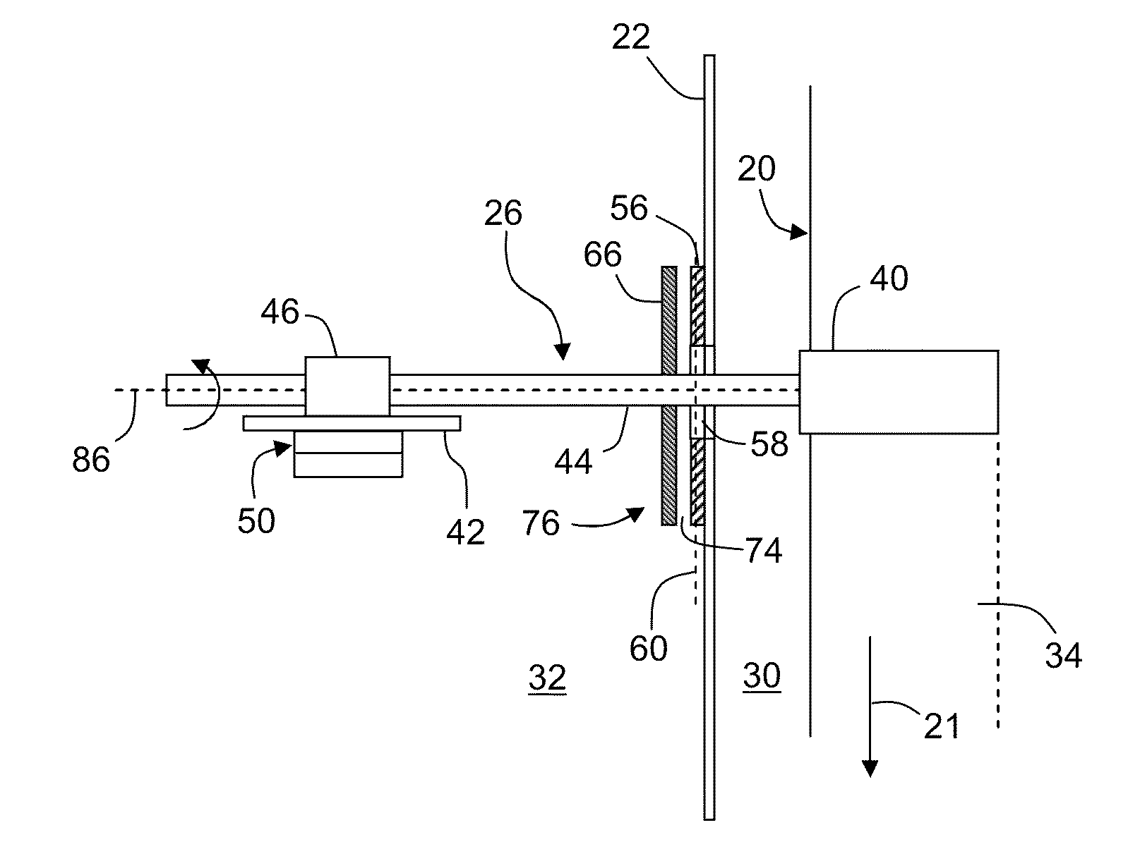
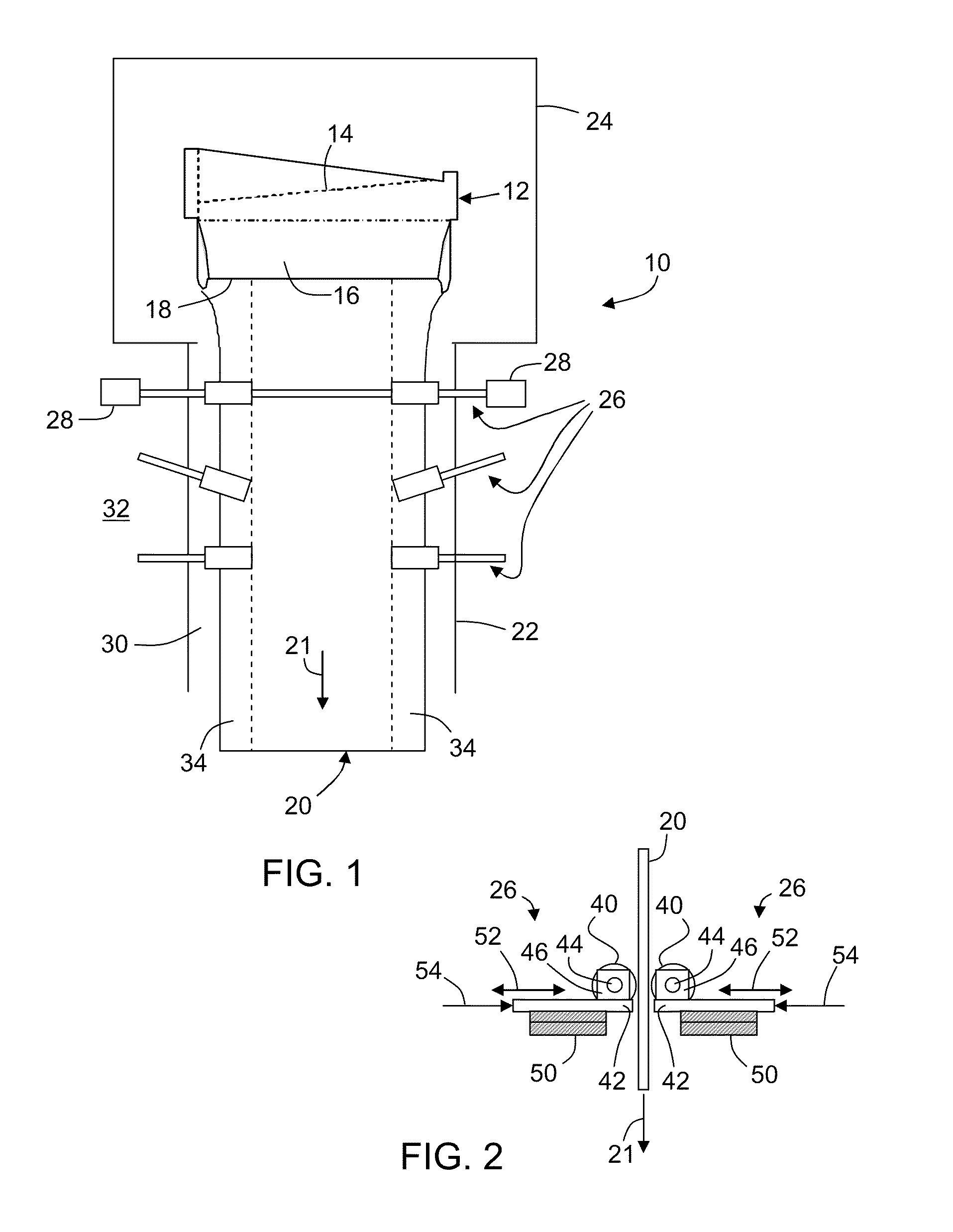
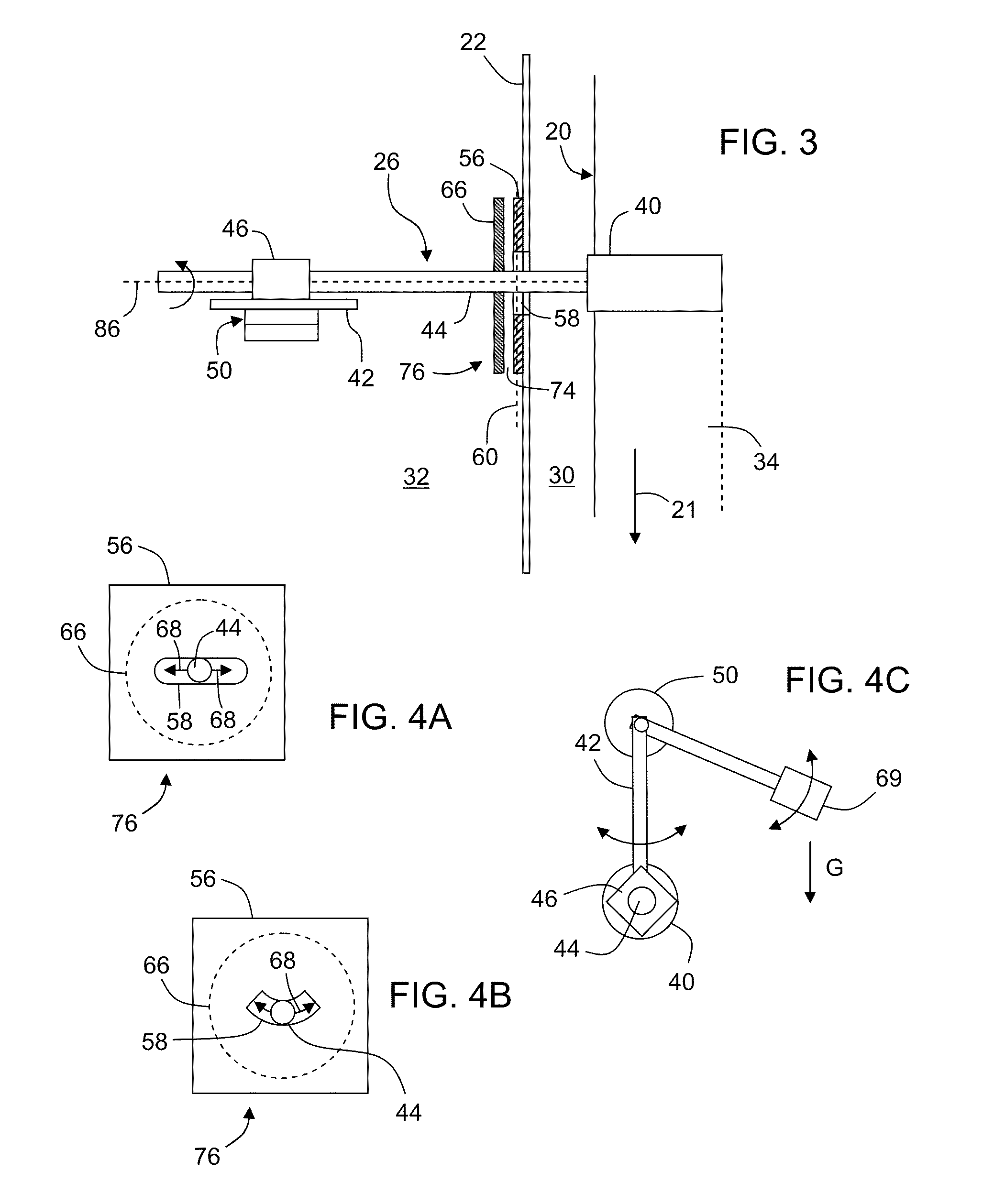
[0033]FIG. 9 is a top cross sectional view showing a pair of edge rolls engaged with an edge of a glass ribbon, further illustrating air bearings coupled with the edge roll shafts via support members and employing seal assemblies.

[0034]FIG. 10 is a cross sectional view of another embodiment of a seal assembly utilizing springs between several seal plates.

DETAILED DESCRIPTION

[0035]In the following detailed description, for purposes of explanation and not limitation, example embodiments disclosing specific details are set forth to provide a thorough understanding of the present invention. However, it will be a...


PUM

PropertyMeasurementUnit
temperaturesaaaaaaaaaa
frictional coefficientsaaaaaaaaaa
pressureaaaaaaaaaa

Abstract

An apparatus for drawing a glass ribbon including a shroud surrounding the glass ribbon and an edge roll that penetrates the shroud to contact the glass ribbon. The apparatus includes regulating a pressure within the seal assembly to be equal to or less than a pressure within the shroud and prevent ingress of relatively cooler outside gas into the hot interior of the shroud. The edge roll utilizes an air bearing to minimize friction that can produce periodic fluctuation of the ribbon as the edge roll is displaces in response to variations in the ribbon thickness or equipment dimensions.

Description

TECHNICAL FIELD[0001]This invention is directed to a method of reducing force cycling in a glass drawing process. An apparatus for drawing glass that reduces force cycling is also disclosed.BACKGROUND[0002]One method of forming a thin sheet of glass is by a drawing process where a ribbon of glass is drawn from a reservoir of molten glass. This may be accomplished, for example, via an up-draw process, where the ribbon is drawn upward from the reservoir (e.g. Foucault or Colburn), or by a down-draw process (e.g. slot or fusion), where the ribbon is drawn downward, typically from a forming body. Once the ribbon is formed, individual sheets of glass are cut from the ribbon.[0003]In a conventional downdraw process, the molten glass is formed into a glass ribbon contained within a draw chamber defined by a shroud that surrounds the ribbon. Among other things the shroud serves to maintain a consistent thermal environment in the region defined by the shroud and surrounding the ribbon. Rolle...

Claims


Application Information

Patent Timeline
Patent Type & Authority Applications(United States)
IPC IPC(8): C03B13/00C03B29/06
CPCC03B17/068C03B17/067
Inventor ANDERSON, JAMES G.KLINGENSMITH, L. KIRKPERIS, JAMES P.ULRICH, DAVID J.
Owner CORNING INC
Why Eureka
Try Eureka