
Inspection device

a technology of ultrasonic testing and scanning device, which is applied in the direction of material magnetic measurements, and solid analysis using sonic/ultrasonic/infrasonic waves. it can solve the problems of loss of scan quality, limited use in production (as opposed to service), and bulky equipmen

Inactive Publication Date: 2011-05-05
AIRBUS OPERATIONS LTD
View PDF12 Cites 9 Cited by
  • Summary
  • Abstract
  • Description
  • Claims
  • Application Information

AI Technical Summary

Benefits of technology

The invention provides an ultrasonic scanner for scanning contoured workpieces. The scanner comprises a body, a first ultrasound transducer with a first scanning vector, and a second ultrasound transducer with a second scanning vector. The transducers are mounted to the body such that their scanning vectors pass through a single focal axis and are perpendicular to each other. The scanner also includes a coupling component that ultrasonically couples the transducers to the workpiece at a coupling surface. The coupling surface can be a fillet radius between two substantially planar surfaces that are at right angles to each other. The scanner can also have a liquid couplant delivery system and a roller element for contacting the workpiece during scanning. The scanning assembly can also include a plurality of ultrasound transducers mounted to the body with scanning vectors that pass through a single focal axis and are perpendicular to each other. The technical effects of the invention include improved accuracy and efficiency in scanning complex workpieces.

Problems solved by technology

This causes reflection of the sound waves and a loss in scan quality if a couplant is not used.
Traditionally, ultrasonic testing has been limited in terms of inspection speed as the operation had to be carried out on a point-by-point basis.
Such equipment however is bulky and limited to use in a production (as opposed to service) environment and is not considered portable.
Scanning of radii and tightly curved areas is a problem.
This causes problems in tightly curved areas, and especially at tight fillet radii found for example at the root of a stringer web.
Such radii are in the order of 5 mm radius and the use of traditional bulky scanners in this area is not effective.
In particular, linear scanning arrays can not project ultrasonic energy normal to the surface of a curved component.

Method used


Image

  • Inspection device
  • Inspection device
  • Inspection device

Examples


Embodiment Construction

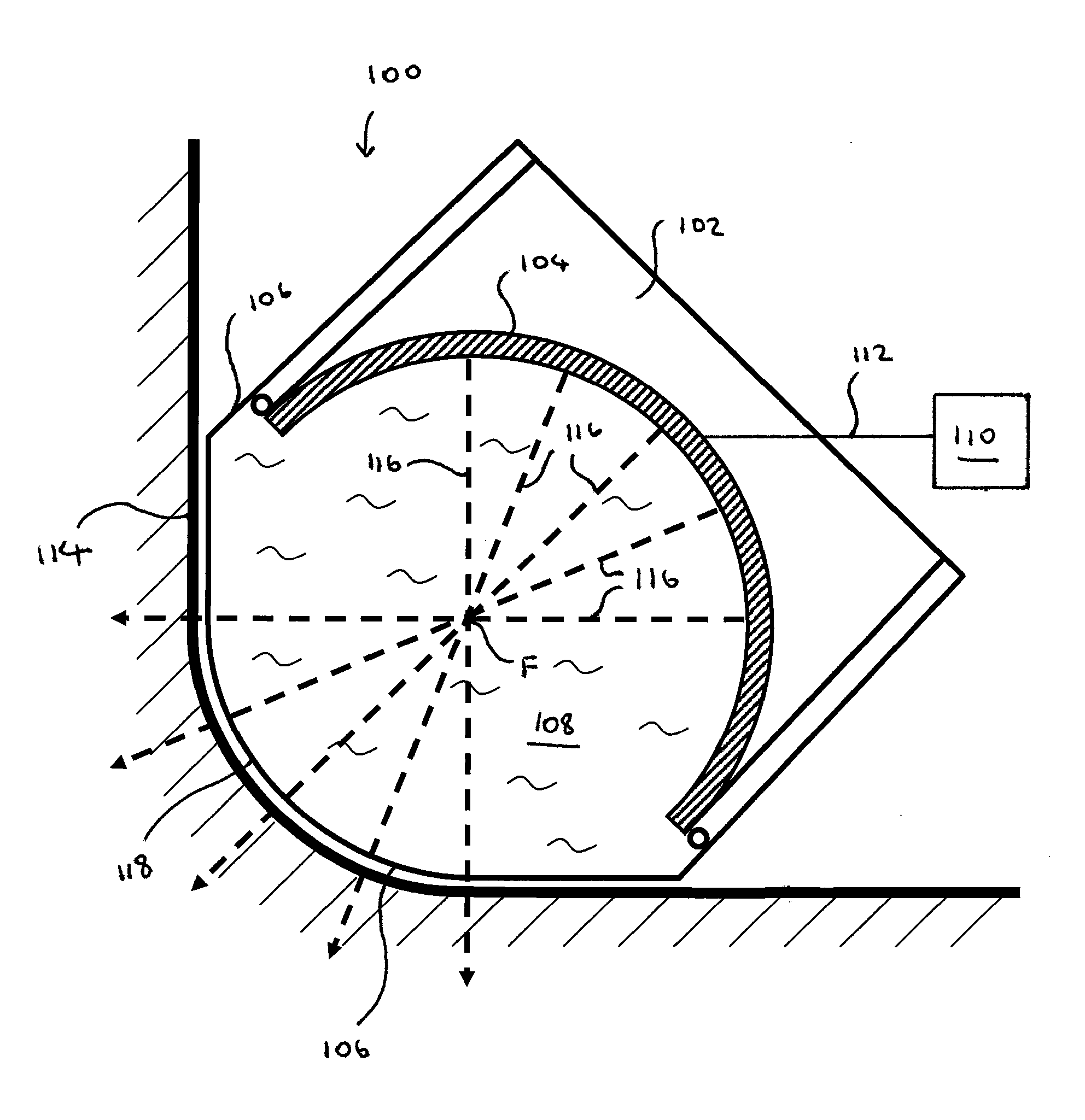
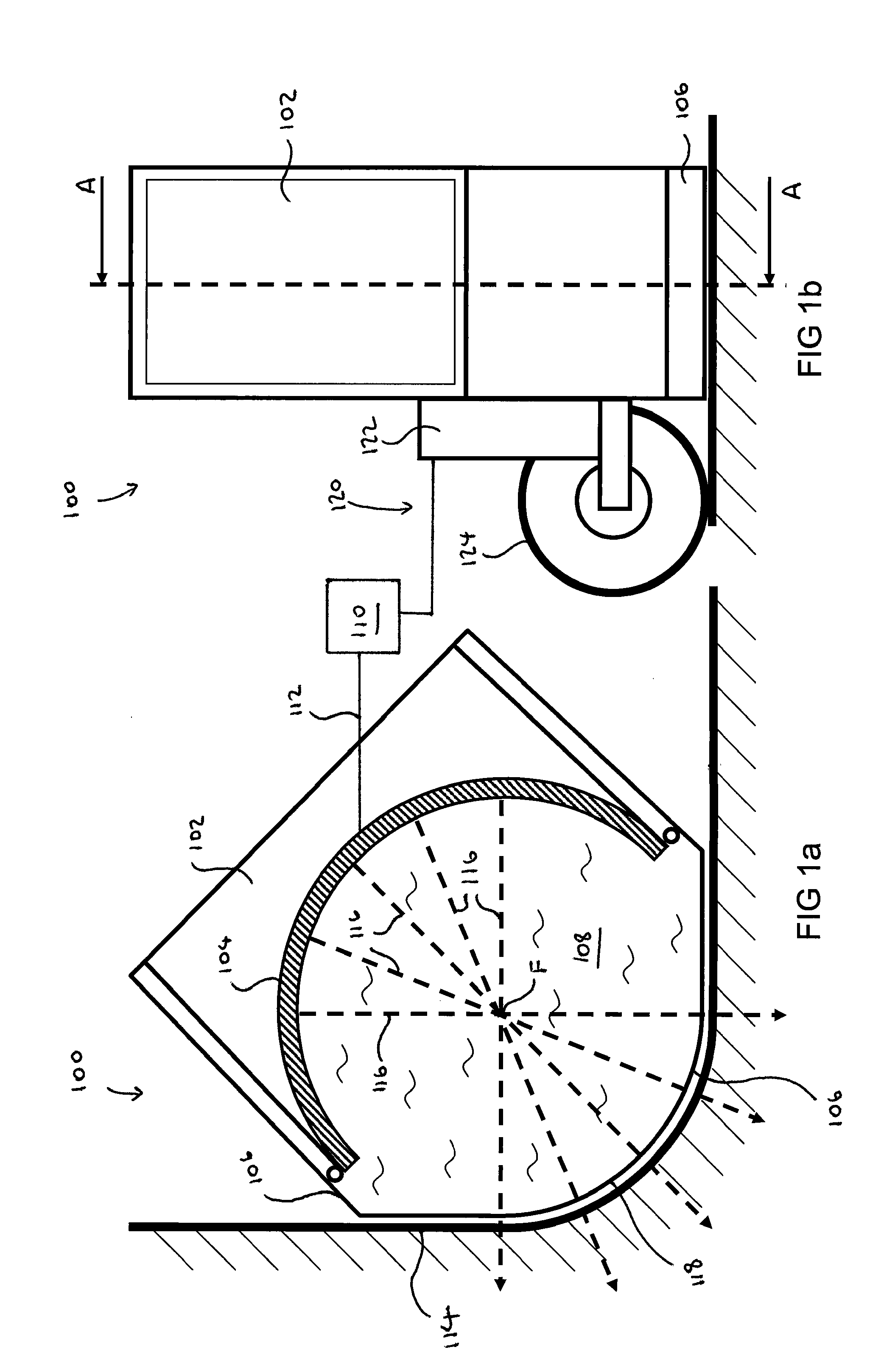
[0052]Referring to FIGS. 1a and 1b, there is provided a scanning device 100 comprising a body 102 housing an ultrasonic scanning array 104. The device 100 further comprises a latex rubber boot 106 connected to the body 102 and enclosing the array 104. The boot 106 is filled with a couplant liquid 108.

[0053]The array 104 is arcuate in form and is connected to a computer 110 via a data connection 112. The array 104 is capable of transmitting and receiving ultrasonic energy for the non-destructive testing of a composite workpiece 114.

[0054]The array 104 emits ultrasonic energy perpendicular to its inner surface, as is shown by example vectors 116. The vectors 116 cross at a focal point F. The outer surface of the boot 106 is shaped in the form of an arc 118 with a geometric centre at the focal point F.

[0055]Turning to FIG. 1b, the device 100 further comprises a rotary encoder 120 comprising a frame 122 and an encoder wheel 124. The encoder wheel 124 is mounted such that it projects as ...


PUM

PropertyMeasurementUnit
radiusaaaaaaaaaa
radiiaaaaaaaaaa
distanceaaaaaaaaaa

Abstract

An ultrasound scanner (100) which has a pluralityofultrasound transducers (104) directed normal to a scanning surface (106) to scan a workpiece (114), the scanner (100) comprising a couplant filled latex rubber sheath (106) shaped to the surface of a workpiece (114).

Description

FIELD OF THE INVENTION[0001]The present invention is concerned with a scanner. More specifically, the present invention is concerned with an ultrasonic testing (UT) scanner for non-destructive testing of metal and composite structures etc.BACKGROUND OF THE INVENTION[0002]Non-visible areas of materials, such as the interiors of components, welds and composite materials can be analysed using ultrasonic testing. This type of non-destructive testing (NDT) utilises the reflection of sound waves to detect faults and features which would otherwise be very difficult to detect without destroying the component in the process. Ultrasonic testing is a common technique in the aerospace sector to test the integrity of materials at manufacture and during service.[0003]Scanners tend to be of the portable type (i.e. more suited to in-service scanning) or non-portable type (specifically for production).[0004]A feature of ultrasonic testing is that a couplant is required to aid transmission of the ult...

Claims


Application Information

Patent Timeline
Patent Type & Authority Applications(United States)
IPC IPC(8): G01N29/28
CPCG01N29/28G01N2291/2638G01N2291/051
Inventor BOND-THORLEY, ANDREW
Owner AIRBUS OPERATIONS LTD
Learn More