Cutting rules for cutting of flat materials

a cutting rule and flat material technology, applied in the direction of saw chains, sawing machines, metal working machines, etc., can solve the problems of insufficient use of flat bed stamping machines, high labor intensity, and time-consuming iterative levelling process, so as to facilitate the introduction of cutting rules into the slots of carrier plates, facilitate the precise definition of plastic deformation, and facilitate the effect of levelling

Inactive Publication Date: 2011-05-05
BOEHLER UDDEHOLM PRECISION STRIP GMBH
View PDF3 Cites 4 Cited by
  • Summary
  • Abstract
  • Description
  • Claims
  • Application Information

AI Technical Summary

Benefits of technology

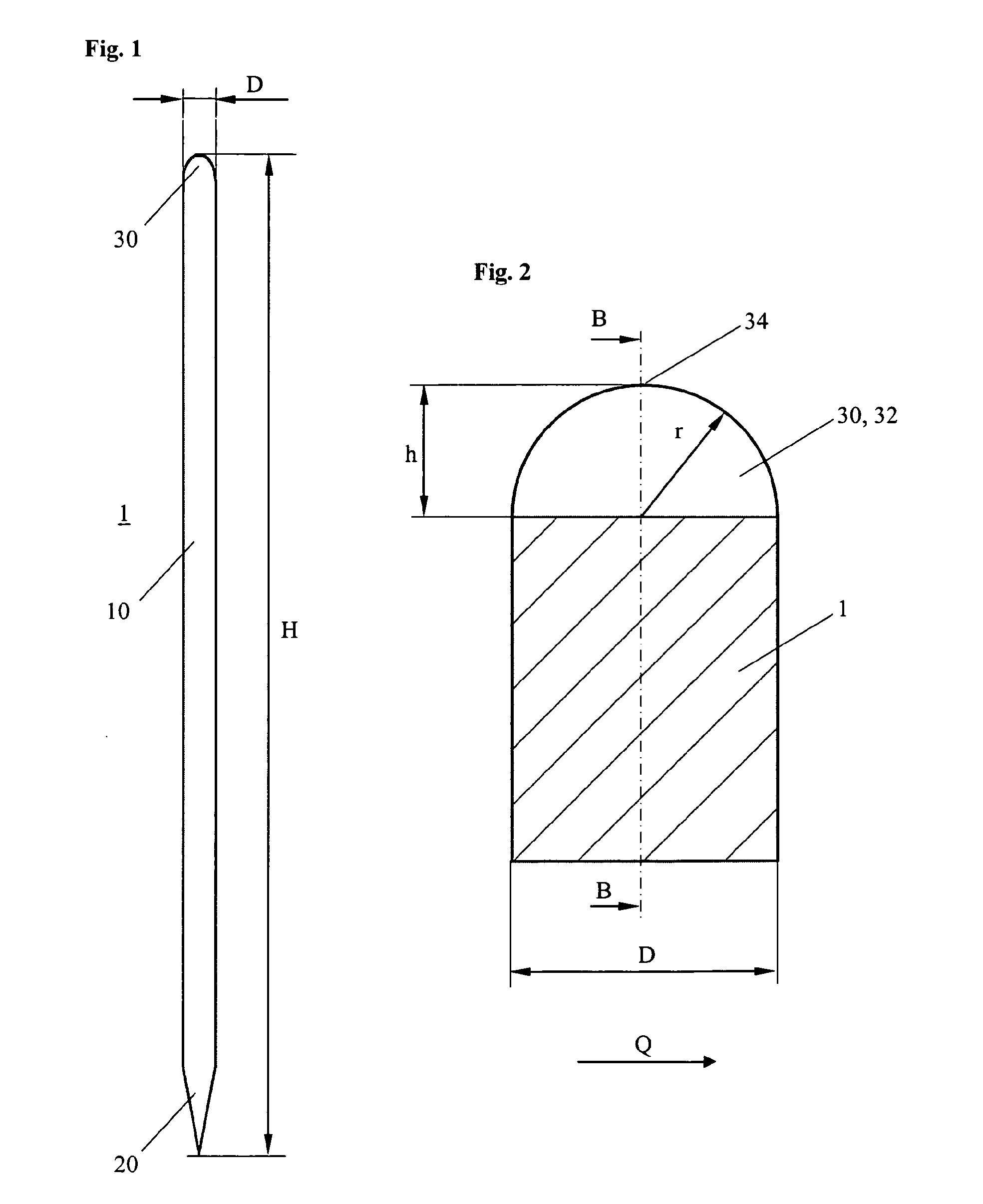
[0026]In a further preferred embodiment, the back is rounded in a cross section through the tip of the protrusions. By this shape of the back, which is additionally rounded in transverse direction, a line or point-shaped abutting face of the back at the back plate of the tool is given, wherein the plastic deformation of the protrusions is further facilitated. Additionally, the introduction of the cutting rules into the slots of the carrier plate is facilitated. Finally, such a cross sectional shape further decreases the effect of the so called back bulging in small bending radiuses. During bending of small radiuses, usually an increase of the total height H of the cutting rule in a range of up to 0.2 mm would happen, depending on the thickness of the cutting rules and the bending radius, what is avoided according to the invention.
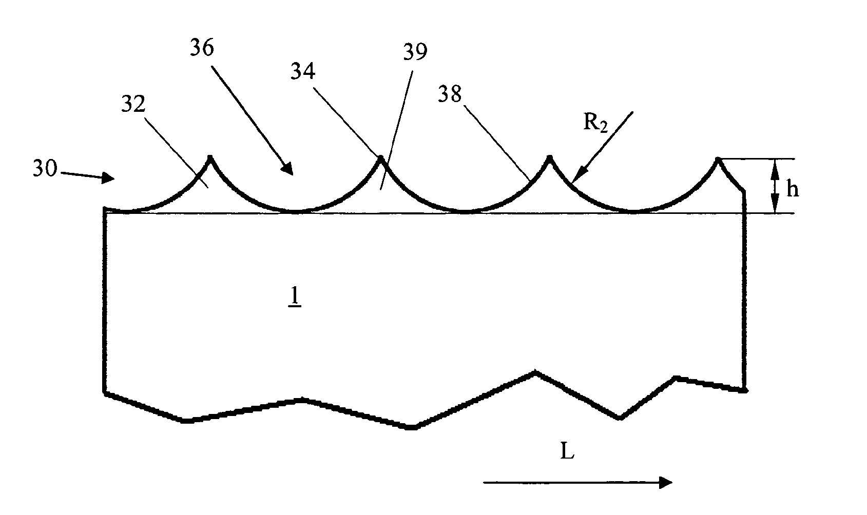
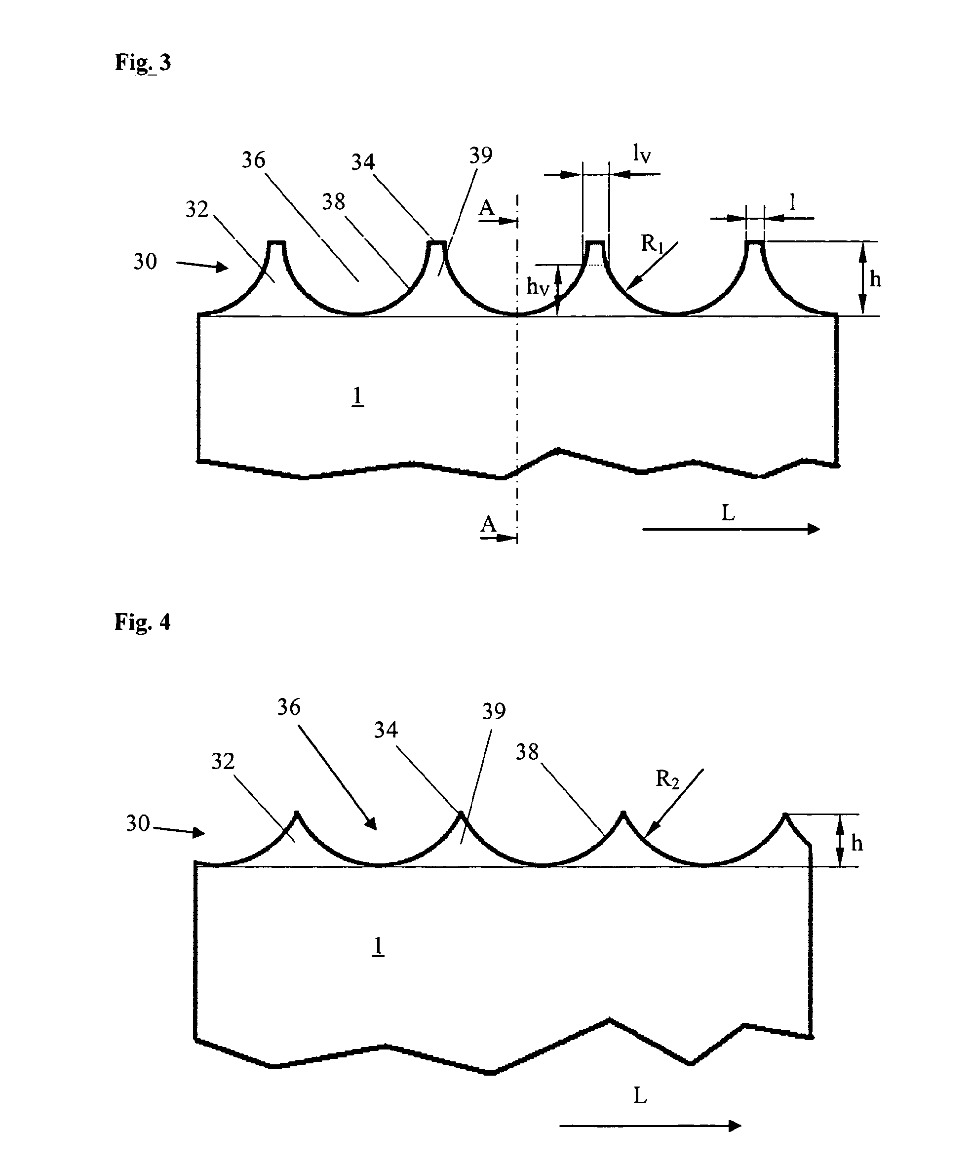
[0027]In another preferred embodiment, the back in a cross section through the tip of the protrusions is chamfered at both sides or double-concave shaped. Also these shapes of the back facilitate an exact defined measure of plastic deformation while providing sufficient stability of the back.
[0028]In a further preferred embodiment, the back in a cross section through the tip of the protrusions is semi-circular rounded, wherein the radius of the rounding r corresponds to the half thickness D of the steel band. This embodiment is particularly preferred with respect to the back bulging, wherein simultaneously a sufficiently high stability of the back of the grooving and cutting rule in transverse direction is provided. By means of the back, being rounded in transverse direction, quasi a central force introduction into the grooving or cutting rule is given, wherein transverse forces are avoided. Thereby, a tilting of the grooving or cutting rule within the slot of the carrier plate is effectively prevented.

Problems solved by technology

Therefore, the levelling is a time-consuming iterative process which requires much experience and in which the flat bed stamping machine cannot be productively used.
Since manual levelling is time-consuming and requires an expensive stop of the machine, there is a need for a method and means for decreasing this effort.
However, the proposed geometries have the disadvantage that they either not lead to the desired result in the desired amount or lead to an instability of the cutting rule, what leads not to a complete height levelling and an inaccurate cutting result.
To this end, cutting rules having such shapes were not accepted by the market.
Further, the cross sections of cutting rules according the prior art would have been very costly in production what would make such rules very expensive.
Further, an automatic processing, in particular an automatic bending of such rule cross sections, would not be possible, or not be possible without edge bulging.

Method used


Image

  • Cutting rules for cutting of flat materials
  • Cutting rules for cutting of flat materials
  • Cutting rules for cutting of flat materials

Examples


Embodiment Construction

[0044]In the following, preferred embodiments of the present invention are described in detail with reference to the figures.

[0045]FIG. 1 shows a first embodiment of a cutting rule 1 according to the invention. The cutting rule 1 essentially consists of a flat steel band 10 with a height H in the range of approximately 8 to 100 mm, a thickness D in the range of 0.45 to 2.13 mm (1.3 to 6 pt), an arbitrary length and a cutting edge 20. Special geometries of the cutting rules—as mentioned above—have other edge shapes 20 and are also subject matter of the present invention.

[0046]Opposed to the cutting edge 20, there is the back 30 of the steel band 10, respectively of the cutting rule 1, which in a preferred embodiment is rounded. In the shown embodiment, the back 30 is semi-circular rounded and has a rounding radius r which corresponds essentially to half of the thickness D of the steel band 10.

[0047]In FIG. 2, a section through the area of the back 30 is shown in detail. Here, particu...


PUM

PropertyMeasurementUnit
depthaaaaaaaaaa
thicknessaaaaaaaaaa
thicknessaaaaaaaaaa

Abstract

The present invention relates to a cutting rule 1, comprising a steel band 10 with a cutting edge 20, a back 30 of the steel band 10 opposite to the cutting edge 20, wherein the back 30 comprises protrusions 32 which during the first use of the cutting rule 1 can be plastically deformed and wherein the protrusions 32 essentially comprise a height h of 30%-70% of the thickness D of the steel band 10. Further, the present invention relates to a cutting rule 1, comprising a steel band 10 with a cutting edge 20, a back 30 of the steel band 10 opposite to the cutting edge 20, wherein the back comprises protrusions 32 that can be plastically deformed during the use of the cutting rule 1 and wherein the protrusions 32 have been produced by grinding or milling of recesses 36 in transverse direction Q of the steel band into the back 30; as well as a cutting rule 1 whose back 30 is surface decarburized such that it can plastically deform during the first use of the cutting rule 1.

Description

1. TECHNICAL FIELD[0001]The present invention relates to cutting rules for cutting of flat materials, particularly paper, cardboard, plastics, etc. The expression cutting rules designates also special kinds like perforating rules or cutting-grooving-combination rules.2. PRIOR ART[0002]Cutting rules are known in the prior art and consist of a steel band with a cutting edge, two parallel side faces and a back opposite to the cutting edge. Cutting rules are bent corresponding to the desired shape of the piece to be cut, cut to a desired length and inserted into a carrier plate. The cutting tool made by this process is for example used for flat bed stamping for example in order to cut cardboard. Usually a flat bed stamping machine comprises a plane upper plate at which the cutting tool is mounted, as well as a plane lower plate by which the work piece is pressed against the cutting tool. The cutting tool comprises a carrier plate provided with slots, usually made of a wood composite, wh...

Claims


Application Information

Patent Timeline
Patent Type & Authority Applications(United States)
IPC IPC(8): B26F1/44
CPCB26F1/44B26F2001/4463B26F2001/4436Y10T83/9295
Inventor HAAS, ANTON
Owner BOEHLER UDDEHOLM PRECISION STRIP GMBH
Why Eureka
Try Eureka